No products
Product successfully added to your shopping cart
There are 0 items in your cart. There is 1 item in your cart.
Electronics
Top sellers
-

Services
1,00 € -

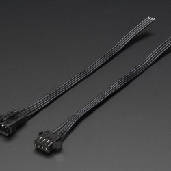
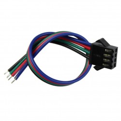
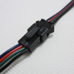
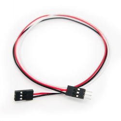
4 Pin Dual-female...
0,85 € -

-

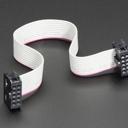
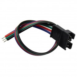
6 Pin Dual-female...
1,89 €


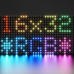
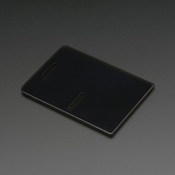
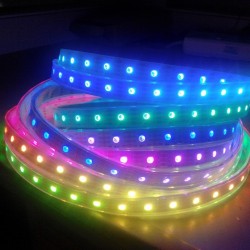
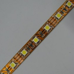
Bring a little bit of Times Square into your home with this 16 x 32 RGB LED matrix panel. These panels are normally used to make video walls, here in New York we see them on the sides of busses and bus stops, to display animations or short video clips. We thought they looked really cool so we picked up a few boxes of them from a factory. They have 512 bright RGB LEDs arranged in a 16x32 grid on the front. On the back there is a PCB with two IDC connectors (one input, one output: in theory you can chain these together) and 12 16-bit latches that allow you to drive the display with a 1:8 scan rate.
These displays are 'chainable' - connect one output to the next input - but our Arduino example code does not support this (yet). It requires a high speed processor and more RAM than the Arduino has!
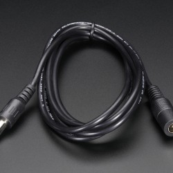
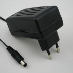
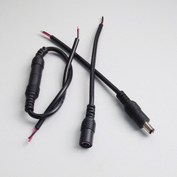
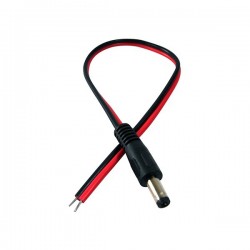
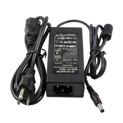
These panels require 12 digital pins (6 bit data, 6 bit control) and a good 5V supply, up to 2A per panel. We suggest our 2A regulated 5V adapter and then soldering a jack on such as from our extension cord. Please check out our tutorial for more details!.
Keep in mind that these displays are designed to be driven by FPGAs or other high speed processors: they do not have built in PWM control of any kind. Instead, you're supposed to redraw the screen over and over to 'manually' PWM the whole thing. On a 16 MHz arduino, we managed to squeeze 12-bit color (4096 colors) with 20% CPU usage but this display would really shine if driven by any FPGA, CPLD, Propeller, XMOS or other high speed multi-core controller. The good news is that the display is pre-white balanced with nice uniformity so if you turn on all the LEDs its not a particularly tinted white.
Of course, we wouldn't leave you with a datasheet and a "good luck!" We have a full wiring diagrams and working Arduino library code with examples from drawing pixels, lines, rectangles, circles and text. You'll get your color blasting within the hour! On an Arduino, you'll need 12 digital pins, and about 800 bytes of RAM to buffer the 12-bit color image. At this time we do not have wiring documentation for the MEGA, but we will update our tutorial in the next week to add MEGA
Please note! These panels are remainder stock from factories that make huge light boards. For that reason, the look, LED tint, power cable style and length, and precise size might vary from batch to batch, even though the basic operation, codebase and tutorial is the same.
We don't have a spec or datasheet at this time. However, these are the specifications from the factory
- Dimensions: 192mm x 96mm x 12mm (7.6" x 3.8" x 0.5")
- Panel weight with IDC cable and power cable: 170 g
- 5V regulated power input, 2.5A max (all LEDs on)
- 5V data logic level input
- 2000 mcd LEDs on 6mm pitch
- 1/8 scan rate
- Indoor display, 150 degree visibility
- Displays are 'chainable' - connect one output to the next input - but our Arduino example code does not support this yet
Tags
 19,90 €
 41,90 €
 99,00 €
 91,50 €
 32,90 €
 32,14 €
 57,99 €
 28,69 €
 91,99 €
 11,45 €

Related Products
-
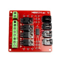
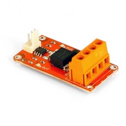
4 Route MOSFET Button
22,99 €Add to cart -
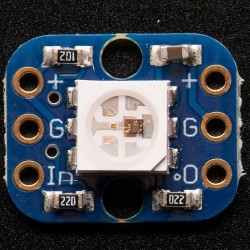
Breadboard-friendly RGB Smart NeoPixel
9,15 €Add to cart -
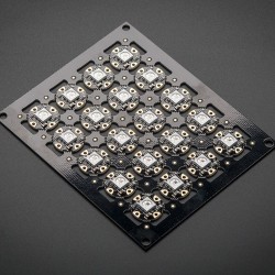
Flora RGB Smart NeoPixel version 2
40,20 €Add to cart -
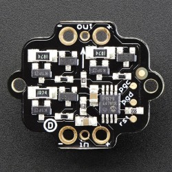
Pixie - 3W Chainable Smart LED Pixel
17,20 €Add to cart -
32x32 RGB LED Matrix Panel - 4mm Pitch
57,99 €Add to cart -
12V EL wire/tape inverter
5,99 €Add to cart -
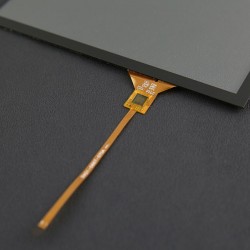
7-inch Capacitive Touch Panel Overlay...
25,89 €Add to cart -
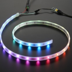
Adafruit NeoPixel LED Strip Starter Pack
28,70 €Add to cart -
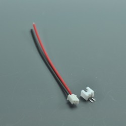
2-pin JST SM In-line power wire...
0,89 €Add to cart -
2-pin JST SM In-line power wire...
0,89 €Add to cart -
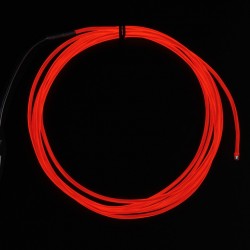
High Brightness Red...
13,80 €Add to cart -
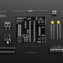
Nootropic RGB Matrix Backpack
22,99 €Add to cart -
Touch overlay
130,00 €Add to cart -
USB Cable, Micro-B to Standard-B...
5,99 €Add to cart -
Barometric...
9,60 €Add to cart -

Digital LED Strip APA102-144 LED/m -...
50,00 €Add to cart -

NeoPixel NeoMatrix 8x8
33,50 €Add to cart -
10-pin IDC Socket Rainbow Breakout Cable
3,40 €Add to cart -
10-pin Socket/Socket IDC cable
1,57 €Add to cart -
10-pin Socket/Socket IDC cable - 6"
2,07 €Add to cart -
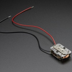
12" Chemical eTape Liquid Level...
65,99 €Add to cart -
12" eTape Liquid Level Sensor + extras
39,95 €Add to cart -
12" Standard eTape Liquid Level...
56,99 €Add to cart -
13.56MHz RFID/NFC Sticker - 1KB
2,89 €Add to cart -

13.56MHz RFID/NFC White Tag - 1KB
2,89 €Add to cart -
2-pin JST SM Plug + Receptacle Cable Set
0,70 €Add to cart -
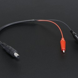
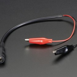
2.1mm DC Barrel Plug to Alligator Clips
2,25 €Add to cart -
20mm Coin Cell Breakout w/On-Off...
8,10 €Add to cart -
3 x AA Battery Holder with On/Off...
3,55 €Add to cart -
3 x AAA Battery Holder with On/Off...
3,49 €Add to cart -
3M Z-Axis Conductive Tape 9703
6,30 €Add to cart -
3x4 Right Angle Male Header - 4 pack
3,50 €Add to cart -
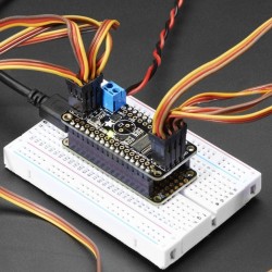
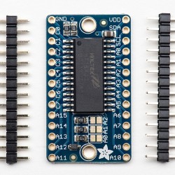
8-Channel PWM or Servo FeatherWing...
11,69 €Add to cart -
Adafruit 16x8 LED Matrix Driver Backpack
6,99 €Add to cart -
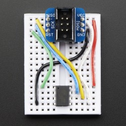
Adafruit 6-pin AVR ISP Breadboard...
1,65 €Add to cart -
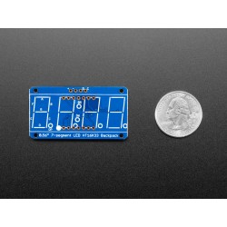
Adafruit 7-Segment LED Matrix Backpack
7,25 €Add to cart -
Adafruit 9-DOF Absolute Orientation...
33,50 €Add to cart -
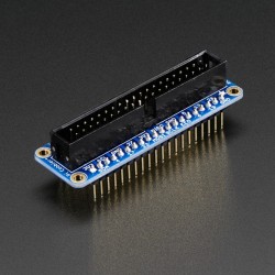
Adafruit Assembled Pi T-Cobbler...
6,95 €Add to cart -
Adafruit BME280 I2C or SPI...
21,90 €Add to cart -
Adafruit DC & Stepper Motor HAT for...
25,89 €Add to cart -
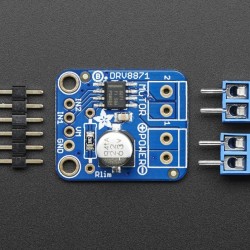
Adafruit DRV8871 DC Motor Driver...
8,90 €Add to cart -
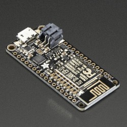
Adafruit Feather HUZZAH with ESP8266...
14,40 €Add to cart -
Adafruit Feather M0 Adalogger
22,30 €Add to cart -
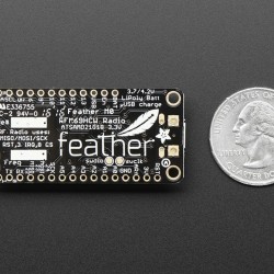
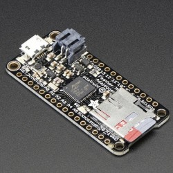
Adafruit Feather M0 RFM69 Packet Radio
25,99 €Add to cart -
Adafruit Half-size Perma
5,10 €Add to cart -
Adafruit HUZZAH ESP8266 Breakout
11,45 €Add to cart -
Adafruit LED Sequins
4,55 €Add to cart -
Adafruit Micro Lipo w/MicroUSB Jack -...
8,15 €Add to cart -
Adafruit Motor/Stepper/Servo Shield...
22,94 €Add to cart -
Adafruit PN532 NFC/RFID Controller...
45,99 €Add to cart -
Adafruit PowerBoost 500 Shield
22,99 €Add to cart -
Adafruit Pro Trinket LiIon/LiPoly...
5,99 €Add to cart -
Adafruit Ultimate GPS FeatherWing
43,50 €Add to cart -
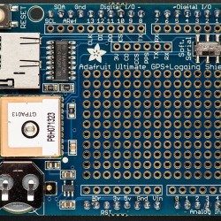
Adafruit Ultimate GPS Logger Shield
49,90 €Add to cart -
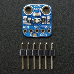
Adafruit VEML6070 UV Index Sensor...
6,89 €Add to cart -
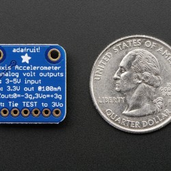
ADXL335 - 5V ready triple-axis...
17,20 €Add to cart -
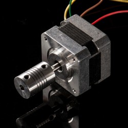
Aluminum Flex Shaft Coupler
5,70 €Add to cart -
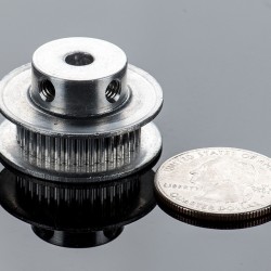
Aluminum GT2 Timing Pulley
9,15 €Add to cart -
Aqua Electroluminescent (EL) Tape Strip
11,99 €Add to cart -
Assembled Drawdio fun pack - v1.1
25,87 €Add to cart -
Assembled Pi Cobbler Plus - Breakout...
6,95 €Add to cart -
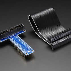
Assembled Pi T-Cobbler Plus - GPIO...
6,99 €Add to cart -
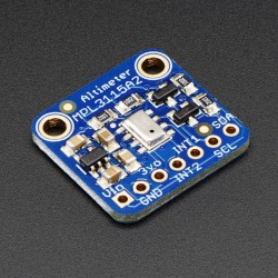
Barometric...
9,60 €Add to cart -
Bone Conductor Transducer with Wires
10,30 €Add to cart -
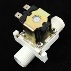
Brass Liquid Solenoid Valve
28,70 €Add to cart -
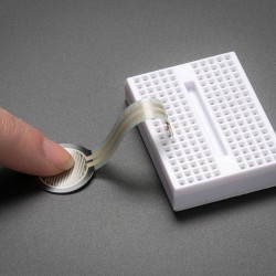
Circular Soft Potentiometer
9,15 €Add to cart -

Conductive Fiber
4,20 €Add to cart -
Conductive Rubber Cord Stretch Sensor...
9,00 €Add to cart -

Conductive thread ribbon cable - Black
6,19 €Add to cart -
Controllable Four Outlet Power Relay...
22,00 €Add to cart -
Copper Foil Tape with Conductive...
6,85 €Add to cart -
Copper Foil Tape wth Conductive...
25,95 €Add to cart -
DE-15 (DB-15) Female Socket to...
5,19 €Add to cart -
DE-15 (DB-15) Male Plug to Terminal...
5,19 €Add to cart -
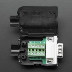
DE-9 (DB-9) Male Plug to Terminal...
3,49 €Add to cart -
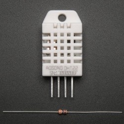
DHT22 temperature-humidity sensor +...
11,45 €Add to cart -
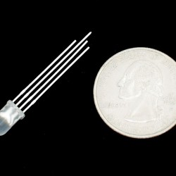
Diffused RGB (tri-color) LED
2,60 €Add to cart -
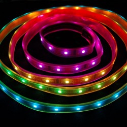
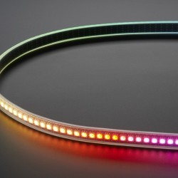
Digital RGB LED Weatherproof Strip-...
34,44 €Add to cart -
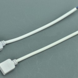
Easy Connector female For LED Strip...
1,59 €Add to cart -
Extra-long break-away 0.1" 16-pin...
3,45 €Add to cart -
Extra-long force-sensitive resistor...
20,69 €Add to cart -
FadeCandy - Dithering USB
28,70 €Add to cart -
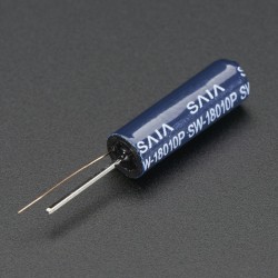
Fast Vibration Sensor Switch
1,10 €Add to cart -
Feather Header Kit
1,05 €Add to cart -
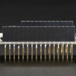
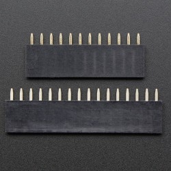
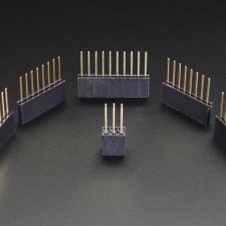
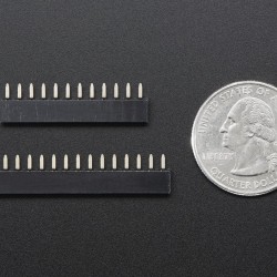
Feather Stacking Headers
1,45 €Add to cart -

Flex PCB Material - Pyralux - 6" by...
12,50 €Add to cart -
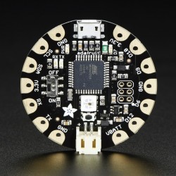
FLORA - Wearable electronic platform
14,60 €Add to cart -
FLORA 9-DOF...
22,99 €Add to cart -
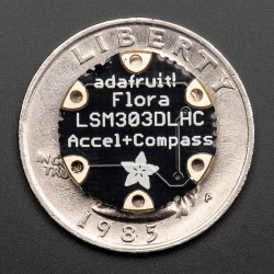
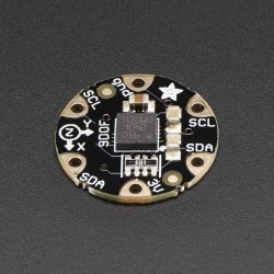
FLORA Accelerometer/Compass Sensor
17,20 €Add to cart -
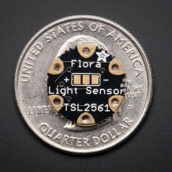
Flora Lux Sensor - TSL2561 Light...
9,15 €Add to cart -
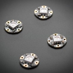
Flora RGB Smart NeoPixel version 2
9,15 €Add to cart -
Flora Sewable 3-Pin JST Wiring Adapter
2,99 €Add to cart -
Flora UV Index Sensor
10,30 €Add to cart -
GPIO Header for Raspberry Pi
2,00 €Add to cart -
GPIO Ribbon Cable for Raspberry Pi...
2,95 €Add to cart -
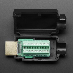
HDMI Plug to Terminal Block Breakout
8,65 €Add to cart -
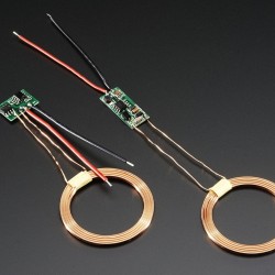
Inductive Charging Set
11,45 €Add to cart -
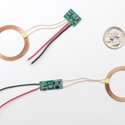
Inductive Charging Set
11,45 €Add to cart -
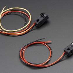
IR Break Beam Sensor
7,95 €Add to cart -
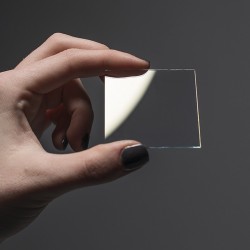
ITO (Indium Tin Oxide) Coated Glass
6,85 €Add to cart -

Keyfob 4-Button RF Remote Control
6,25 €Add to cart -
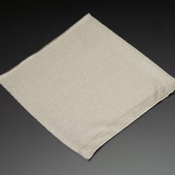
Knit Conductive Fabric
11,45 €Add to cart -

Knit Jersey Conductive Fabric
10,30 €Add to cart -
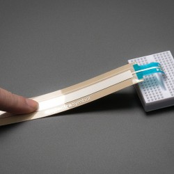
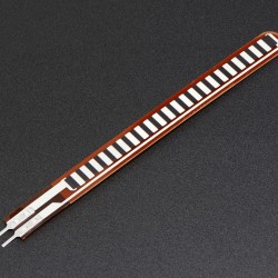
Linear SoftPot (Ribbon Sensor) - 100mm
8,23 €Add to cart -
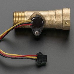
Liquid Flow Meter
28,70 €Add to cart -
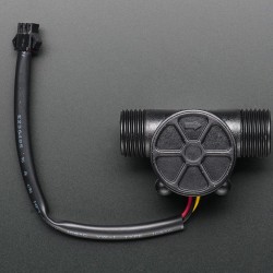
Liquid Flow Meter
11,45 €Add to cart -
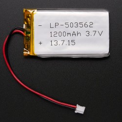
Lithium Ion Polymer Battery - 3.7v...
9,90 €Add to cart -
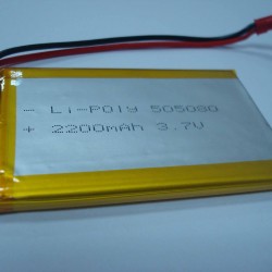
Lithium Ion Polymer Battery - 3.7v...
15,10 €Add to cart -
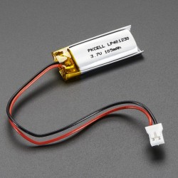
Lithium Ion Polymer Battery 3.7v 100mAh
5,99 €Add to cart -
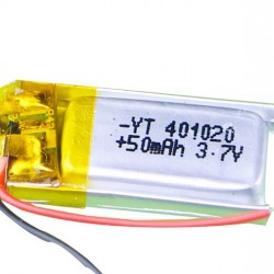
Lithium Ion Polymer Battery 3.7v 50mAh
2,65 €Add to cart -
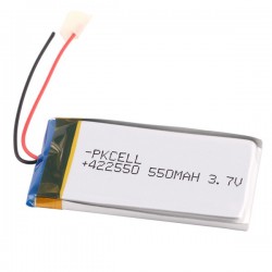
Lithium Ion Polymer Battery 3.7v 550mAh
7,90 €Add to cart -
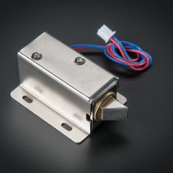
Lock-style Solenoid - 12VDC
14,99 €Add to cart -

Long Flex/Bend sensor
14,98 €Add to cart -
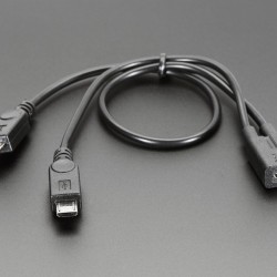
Micro B USB 2-Way Y Splitter Cable
3,49 €Add to cart -
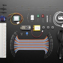
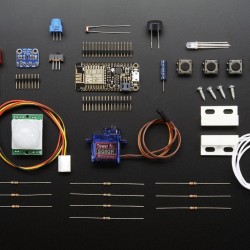
Microsoft Azure IoT Starter Kit w
49,50 €Add to cart -
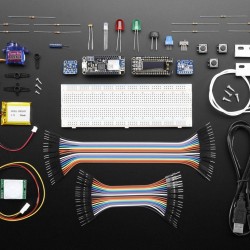
Microsoft Azure IoT Starter Kit w
110,70 €Add to cart -
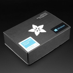
Microsoft IoT Pack for Raspberry Pi 3 -
119,70 €Add to cart -
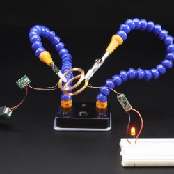
Mini Hand from Hobby Creek with Two Arms
34,50 €Add to cart -

Miniature Slip Ring
22,90 €Add to cart -
Miniature Slip Ring
16,20 €Add to cart -
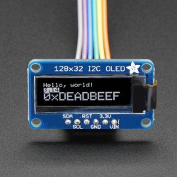
Monochrome 128x32 I2C OLED graphic...
20,15 €Add to cart -
NeoPixel 1/4 60 Ring - WS2812 5050...
11,45 €Add to cart -
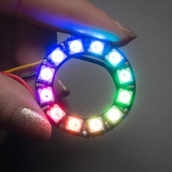
NeoPixel Ring - 12 x WS2812 5050 RGB...
8,50 €Add to cart -
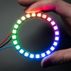
NeoPixel Ring - 24 x WS2812 5050 RGB...
22,94 €Add to cart -
NeoPixel Shield for Arduino - 40 RGB...
32,14 €Add to cart -
Panel Mount HDMI Socket Breakout
4,05 €Add to cart -
Peristaltic Liquid Pump with Silicone...
26,50 €Add to cart -
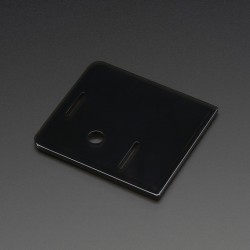
Pi Model B+ / Pi 2 Case Base
4,99 €Add to cart -
PIR (motion) sensor
8,90 €Add to cart -
Plastic Water Solenoid Valve
7,10 €Add to cart -
Pomona Female 0.1" Socket to Banana Plug
9,29 €Add to cart -

Precision Straight Tweezers
9,95 €Add to cart -

Pressure-Sensitive Conductive Sheet...
4,50 €Add to cart -
Professional Non-Slip Magnetic...
24,95 €Add to cart -
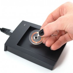
RFID RFID/NFC S50 Card Reader
37,90 €Add to cart -
Round Force-Sensitive Resistor (FSR)
7,24 €Add to cart -
Shield stacking headers for Arduino...
2,25 €Add to cart -
Short Flex/Bend Sensor
6,67 €Add to cart -
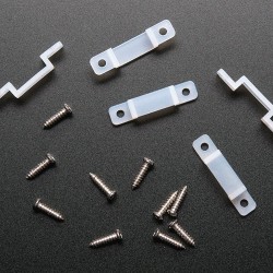
Silicone Clips and Screws for...
2,25 €Add to cart -
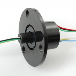
Slip Ring with Flange
13,90 €Add to cart -
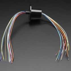
Slip Ring with Flange
18,00 €Add to cart -
Soft Potentiometer Kit from Plug&Wear
10,49 €Add to cart -
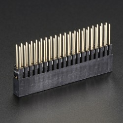
Stacking Header for Pi A+/B+/Pi 2
3,40 €Add to cart -
Stacking Header for Raspberry Pi
2,25 €Add to cart -
Stainless Medium Conductive Thread
8,00 €Add to cart -
Stainless Steel Conductive Ribbon...
26,99 €Add to cart -
Stainless Thin Conductive Thread
7,15 €Add to cart -

Standalone 5-Pad Capacitive Touch...
8,65 €Add to cart -
Sugru - Black and White Pack
19,99 €Add to cart -
Universal Qi Wireless Charging Module
32,10 €Add to cart -
USB LiIon/LiPoly charger - v1.2
14,99 €Add to cart -
White LED Backlight Module
2,25 €Add to cart -
Woven Conductive Fabric
5,70 €Add to cart -
1/4" to 1/4" Screw Adapter
1,75 €Add to cart -
10-pin 2x5 Socket-Socket 1.27mm IDC...
3,40 €Add to cart -

13.56MHz RFID/NFC Bracelet - 1KB
4,69 €Add to cart -
16-Channel PWM / Servo HAT for...
20,15 €Add to cart -
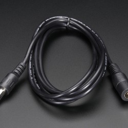
2.1mm female/male barrel jack...
3,40 €Add to cart -
4-pin JST SM Plug + Receptacle Cable Set
1,75 €Add to cart -
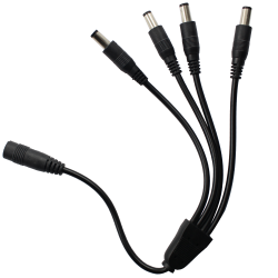
4-Way 2.1mm DC Barrel Jack Splitter
5,70 €Add to cart -

6-pin Socket/Socket IDC cable - 6"
2,30 €Add to cart -
Adafruit 0.56" 4-Digit 7
13,75 €Add to cart -
Adafruit 10-DOF IMU Breakout
34,45 €Add to cart -
Adafruit Capacitive Touch HAT for...
17,20 €Add to cart -
Adafruit GEMMA v2
11,45 €Add to cart -
Adafruit RGB Matrix HAT + RTC for...
28,69 €Add to cart -
Adafruit Triple-Axis Accelerometer
9,15 €Add to cart -
Aluminum Flex Shaft Coupler
5,70 €Add to cart -
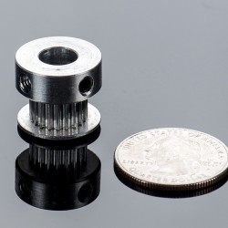
Aluminum GT2 Timing Pulley
13,75 €Add to cart -

Aluminum GT2 Timing Pulley
13,75 €Add to cart -
Aluminum GT2 Timing Pulley
9,15 €Add to cart -
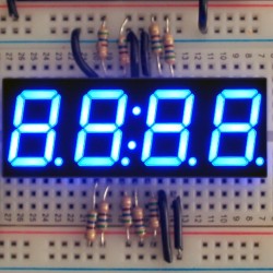
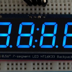
Blue 7-segment clock display
6,85 €Add to cart -
Camera and Tripod 3/8" to 1/4"...
1,75 €Add to cart -
Diffused 5mm Slow Fade Flashing RGB LED
5,70 €Add to cart -
GPIO Header for Raspberry Pi A+/B+/Pi 2
1,75 €Add to cart -
GPS Antenna - External Active Antenna
14,90 €Add to cart -
Huzzah! Adafruit.io Internet of...
43,65 €Add to cart -
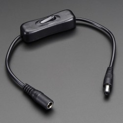
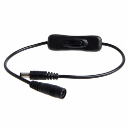
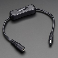
In-line power switch for 2.1mm barrel...
2,90 €Add to cart -
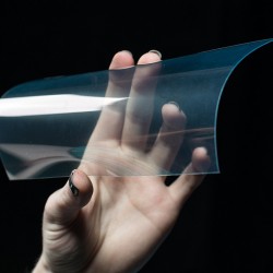
ITO (Indium Tin Oxide) Coated PET...
11,45 €Add to cart -
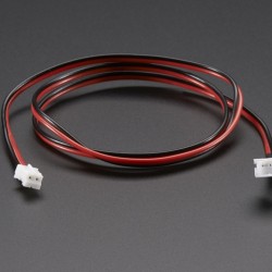
JST-PH Battery Extension Cable - 500mm
2,95 €Add to cart -
Linear Ball Bearing
3,40 €Add to cart -
Magnetic contact switch (door sensor)
4,55 €Add to cart -
Micro servo
6,85 €Add to cart -
Needle set - 3/9 sizes
2,25 €Add to cart -
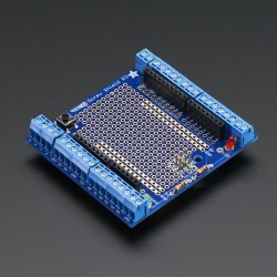
Proto-Screwshield (Wingshield) R3 Kit...
17,19 €Add to cart -
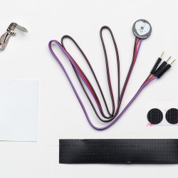
Pulse Sensor Amped
28,75 €Add to cart -
Raspberry Pi Model A+ Case Lid
2,30 €Add to cart -
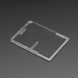
Raspberry Pi Model B+ / Pi 2 Case Lid
3,45 €Add to cart -
Raspberry Pi Model B+ / Pi 2 Case Lid
3,45 €Add to cart -
Sewable Electroluminscent (EL) Wire...
22,99 €Add to cart -
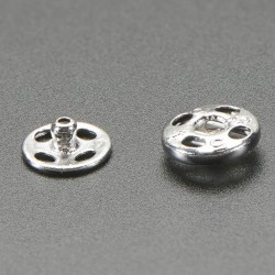
Sewable Snaps - 5mm Diameter
4,55 €Add to cart -
Short Feather Headers Kit
1,75 €Add to cart -
Small Alligator Clip Test Lead
4,55 €Add to cart -
Stainless Thin Conductive Yarn /...
5,19 €Add to cart -
Super Bright Blue 5mm LED
9,20 €Add to cart -
Super Bright White 5mm LED
8,00 €Add to cart -
Universal Qi Wireless Receiver Module
17,20 €Add to cart -
12mm Diffused Thin Digital RGB LED...
39,99 €Add to cart -
DMX USB pro Enttec
149,00 €Add to cart -
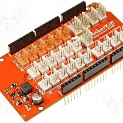
Rainbowduino RGB Matrix Shield
41,90 €Add to cart -
RGB digital led strip APA102 144 leds...
245,00 €Add to cart -
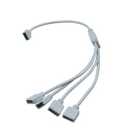
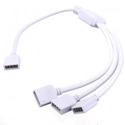
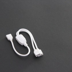
RGB Splitter Cable 1 to 4 Female...
4,80 €Add to cart -

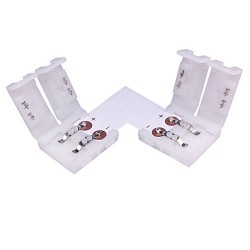
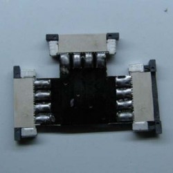
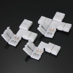
10MM L Shape Snap Down 5050 RGB LED...
2,05 €Add to cart -

10MM Snap Down Strip to Strip RGB LED...
0,90 €Add to cart -
10MM Snap Down Strip to Strip With...
1,80 €Add to cart -
10MM Snap Down Strip Wire LED Strip...
1,50 €Add to cart -
10MM T Shape Snap Down 5050 RGB LED...
2,34 €Add to cart -
10MM X Shape Snap Down 5050 RGB LED...
2,74 €Add to cart -
4 PIN waterproof connector male and...
5,17 €Add to cart -
64x32 RGB LED Matrix - 3mm pitch
91,99 €Add to cart -
Black RGB Splitter Cable 1 to 3...
4,20 €Add to cart -
DC 5.5/2.1 Waterproof Connector Male...
2,25 €Add to cart -
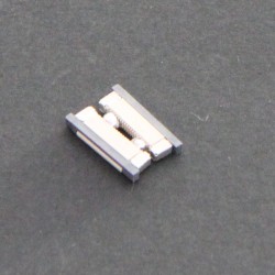
LED RGB Junction Box 4Pin LED RGB...
2,41 €Add to cart -
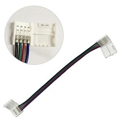
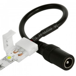
New 10mm 4PIN LED Strip lengthen...
3,25 €Add to cart -
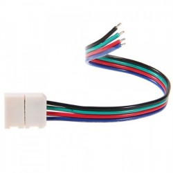
New 10mm 4PIN Strip Wire Solderless...
2,20 €Add to cart -

pins male copper electroplated for...
0,22 €Add to cart -
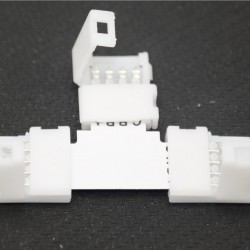
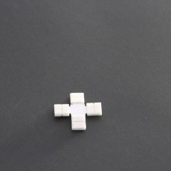
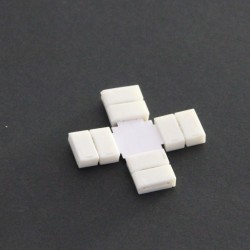
RGB 4 pin "L" "T" ''+" "一" type...
1,94 €Add to cart -
RGB digital led strip APA102 30 leds...
68,90 €Add to cart -
RGB Splitter Cable 1 to 2 Female...
3,50 €Add to cart -
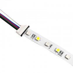
White 4 Pins RGB Strip Connect Female...
1,25 €Add to cart -
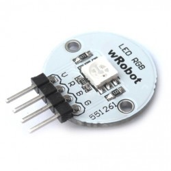
Wrobot Full Color RGB LED Module -A
4,60 €Add to cart -
Flexible LED matrix-8x32 pixels
91,50 €Add to cart -
Mean Well Switching power supply 350w 5v
94,50 €Add to cart -
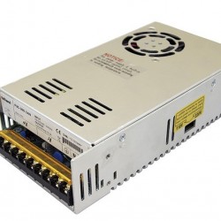
Power supply 300w 5V 60amp
48,50 €Add to cart -
Flexible LED Matrix 16*16
99,00 €Add to cart -
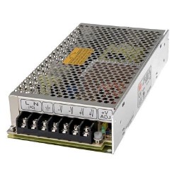
Power supply 100w 5V 20amp
24,50 €Add to cart -
RGB digital led strip APA102 60 leds...
106,80 €Add to cart -
Wire 20AWG 4pin JST SM
0,99 €Add to cart -
Wire 20AWG 4pin JST SM
0,99 €Add to cart -
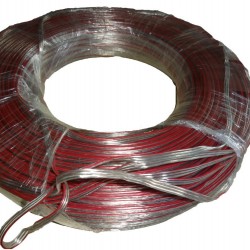
Wire AWG 20AWG RGB 50m/roll
23,90 €Add to cart -
5050 SMD LENs, Angle:10,30,60,120 beam
39,00 €Add to cart -
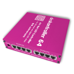
DESKONTROLLER 64, ART-NET LED CONTROLLER
1 590,00 €Add to cart -
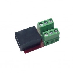
DESKONTROLLER 64, RJ45 TO SCREW...
3,00 €Add to cart -
Easy Connector male For LED Strip...
1,59 €Add to cart -
Flexible LED matrix 8*8
32,90 €Add to cart -
OctoWS2811 Adaptor for Teensy 3.2
12,49 €Add to cart -
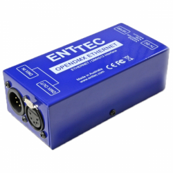
OPEN DMX ETHERNET ODE ENTTEC
260,00 €Add to cart -
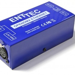
Open DMX Ethernet with poe Enttec
295,00 €Add to cart -
UL Certificated LED Power Supply...
8,80 €Add to cart -

UL Certificated LED Power Supply...
10,50 €Add to cart -

10MM "L" Type LED connector (for SMD...
2,20 €Add to cart -

10MM "T" Type LED connector (for SMD...
2,59 €Add to cart -
10MM L Shape Snap Down 5050/5630 LED...
2,05 €Add to cart -
10MM Strip to Strip LED connector
1,16 €Add to cart -

10MM Strip to Strip with wire LED...
1,46 €Add to cart -
10MM Strip wire LED Coupler
1,16 €Add to cart -
10MM X Shape Snap Down 5050/5630 LED...
2,74 €Add to cart -
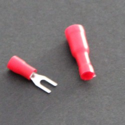
12-10 AWG 1/4in Heat Shrink Snap Spade
1,85 €Add to cart -
2 pin waterproof connector (single...
3,89 €Add to cart -
4 Pin "+" Type Connector
3,60 €Add to cart -
8MM "+" Type LED connector (for SMD...
2,85 €Add to cart -
8MM "L" Type LED connector
2,30 €Add to cart -
8MM "T" Type LED connector (for SMD...
2,30 €Add to cart -
8MM Strip LED connector with DC Plug...
1,40 €Add to cart -
8MM Strip to Strip with wire LED...
1,45 €Add to cart -
8MM X Shape Snap Down 3528 LED Strip...
1,91 €Add to cart -
Dc Connect Male Female LED Power Supply
1,60 €Add to cart -
DC Female Plug with 2PIN JST Connector
0,99 €Add to cart -
DC LED 2-Way Splitter Plug
2,59 €Add to cart -
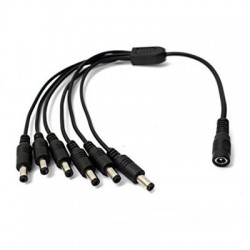
DC LED 8-Way Splitter Plug
7,30 €Add to cart -
DC Male Plug Cable
1,30 €Add to cart -
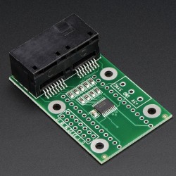
DESKONTROLLER 64, RJ45 SPLITTER
5,00 €Add to cart -
Easy Connector Quick Fix Spring Clamp...
0,45 €Add to cart -
Flexible InfraRed (850nm) SMD5050...
15,20 €Add to cart -
Flexible InfraRed (850nm) SMD5050...
8,50 €Add to cart -

H2519 LED Connector LED 5Pin Terminal...
1,80 €Add to cart -
Heavy Duty Industrial Series Adapter...
18,07 €Add to cart -

Heavy Duty Industrial Series Adapter...
74,99 €Add to cart -

Heavy Duty Industrial Series Adapter...
39,95 €Add to cart -
Infrared (850nm) LED Linear Rigid...
25,78 €Add to cart -
InfraRed flexible LED Strips...
14,29 €Add to cart -
InfraRed LED Strips SMD3528-1200-IR...
29,89 €Add to cart -
InfraRed LED Strips SMD3528-300-IR...
12,10 €Add to cart -
InfraRed Led Strips SMD3528-600-IR...
19,36 €Add to cart -
InfraRed LED Strips SMD5050-600-IR...
39,71 €Add to cart -
InfraRed LED Strips Waterproof IP65...
26,95 €Add to cart -
InfraRed LED Strips Waterproof IP65...
37,09 €Add to cart -
IP65 waterproof strip connector for...
3,90 €Add to cart -

IP65 waterproof strip connector for...
3,25 €Add to cart -
LED Connector 3Pin Terminal Connector
0,55 €Add to cart -
LED Connector Male Female 2 Pin...
0,65 €Add to cart -
LED Strip Light DC Connector With Two...
2,16 €Add to cart -
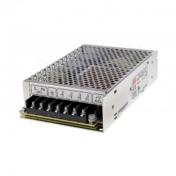
Mean Well power supply 100w 5V 20amp
59,00 €Add to cart -

Power supply 200w 5V 40 amp
33,50 €Add to cart -

UL Certificated LED Power Supply...
14,99 €Add to cart -
UL Certificated LED Power Supply...
20,13 €Add to cart -

White DC Connector 22 AWG 16cm Female...
1,75 €Add to cart -
Wire 20AWG 4pin JST SM 25cm
1,49 €Add to cart -
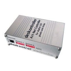
Deskontroller 32, Art-Net LED Controller
1 100,00 €Add to cart -
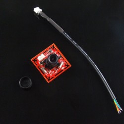
0.3M pixel serial JPEG camera module
51,75 €Add to cart -
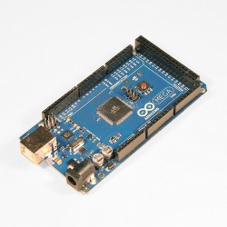
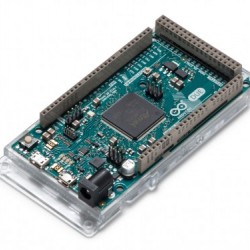
Arduino Mega2560 Rev3
32,00 €Add to cart -
Arduino Uno WiFi
36,90 €Add to cart -
Digital Output-Port Shield V2.0
10,39 €Add to cart -
Gravity: Digital Vibration Sensor
5,18 €Add to cart -
Chibitronics Starter Kit
32,99 €Add to cart -
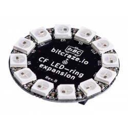
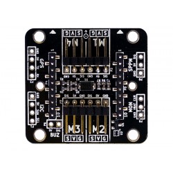
Crazyflie 2.0 - LED-ring Expansion Board
22,00 €Add to cart -
Expansion Pack
53,10 €Add to cart -
Infrared Led Ribbon 5M
210,00 €Add to cart -
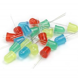
LED various colors 10mm 20x
5,85 €Add to cart -
Tinkerkit DMX Receiver
40,00 €Add to cart -
10MM Snap Down Strip LED connector...
1,55 €Add to cart -

10MM T Shape Snap Down 5050/5630 LED...
2,34 €Add to cart -

18AWG Female LED Power Supply DC...
1,30 €Add to cart -
18AWG Male LED Power Supply DC Cable...
1,30 €Add to cart -
2 Pin Push in Male Female Waterproof...
1,99 €Add to cart -

3M PE Foam Double-sided Adhesive...
0,20 €Add to cart -
55 meters 3M 200MP Double Stick Tape...
20,54 €Add to cart -

55 meters 3M 200MP Double Stick Tape...
25,74 €Add to cart -
8MM L Shape Snap Down 3528 LED Strip...
1,45 €Add to cart -

8MM Snap Down Strip LED connector...
1,50 €Add to cart -
8MM Snap Down Strip to Strip LED...
0,90 €Add to cart -
8MM Snap Down Strip to Strip With...
1,20 €Add to cart -
8MM Snap Down Strip Wire LED Strip...
1,15 €Add to cart -
8MM T Shape Snap Down 3528 LED Strip...
1,95 €Add to cart -
Black TWO 2Pin LED Extension Tinned...
1,10 €Add to cart -
DC Female Plug Cable
1,30 €Add to cart -
DC LED 4-Way Splitter Plug
3,87 €Add to cart -
DC LED 6-WAY SPLITTER PLUG
5,85 €Add to cart -
Extension with DC Plug
2,85 €Add to cart -
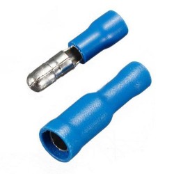
FRD(MPD)1-156 Male/Female Combo Wire...
4,50 €Add to cart -

H2519 LED Connector LED 2Pin Terminal...
0,90 €Add to cart -
H2519 LED Connector LED 3Pin Terminal...
1,20 €Add to cart -
InfraRed Flexible LED Strips...
23,39 €Add to cart -
InfraRed LED Strips SMD3528-30-IR...
14,16 €Add to cart -
IP65 waterproof strip splice connector
1,45 €Add to cart -
Key Switch with DC Plug
6,44 €Add to cart -
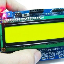
Keypad LCD Shield V2.0 -Arduino...
20,69 €Add to cart -
Led Light DC Switch On-Off Button
2,55 €Add to cart -
LED Strip Light DC Connector With Two...
2,16 €Add to cart -

Prop Shield With Motion Sensors
22,49 €Add to cart -
Prop Shield, Low Cost (no Motion...
9,69 €Add to cart -
TinkerKit Power LED module
8,90 €Add to cart -
White 20 AWG DC Extension
2,10 €Add to cart -
4 Pin Dual-female Jumper Wire - 200mm
0,85 €Add to cart -
4N35 Optocoupler
0,90 €Add to cart -
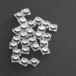
5 PushButton 6x6
1,99 €Add to cart -
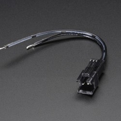
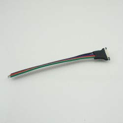
6 Pin Dual-female Jumper Wire -600mm
1,89 €Add to cart -
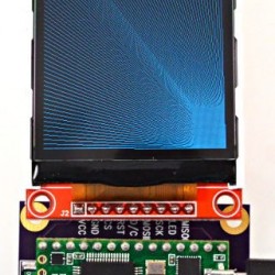
Arduino 1.77 inch SPI LCD Module with SD
17,10 €Add to cart -
Arduino Due
39,99 €Add to cart -
Arduino ETHERNET shield 2 (without PoE)
20,00 €Add to cart -
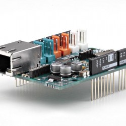
Arduino ETHERNET shield 2 CON PoE -...
33,50 €Add to cart -
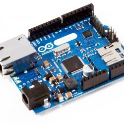
Arduino Ethernet WITHOUT Poe
39,90 €Add to cart -
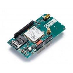
Arduino GSM Shield 2 (antenna connector)
59,50 €Add to cart -
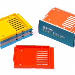
Arduino Holder type Uno
7,12 €Add to cart -
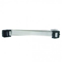
Arduino IDC-6 Special Cable-10cm
1,95 €Add to cart -
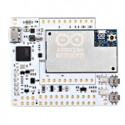
Arduino Industrial 101
32,50 €Add to cart -
Arduino Leonardo (+headers)
17,20 €Add to cart -
Arduino Leonardo ETH WITH PoE
51,90 €Add to cart -
Arduino Leonardo ETH without PoE
39,90 €Add to cart -
Arduino LilyPad USB ATmega 32U4
19,50 €Add to cart -
Arduino Lucky Shield w/BME280
59,00 €Add to cart -
Arduino M0
18,00 €Add to cart -
Arduino Micro
18,90 €Add to cart -
Arduino Nano
18,50 €Add to cart -
Arduino Sensor Extension Cable-30cm
1,80 €Add to cart -
Arduino Tian
87,00 €Add to cart -
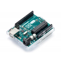
Arduino Uno Rev3 with Long Pins
19,80 €Add to cart -
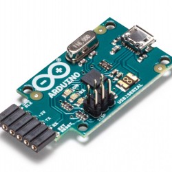
Arduino USB 2 Serial Micro
10,00 €Add to cart -
Arduino USB Host Shield
21,60 €Add to cart -

Arduino Yun
55,80 €Add to cart -
Arduino YUN mini
56,00 €Add to cart -
Box for Arduino
7,02 €Add to cart -
Box for Arduino YUN
7,11 €Add to cart -
Crazyflie 2.0 - BigQuad Deck
8,00 €Add to cart -
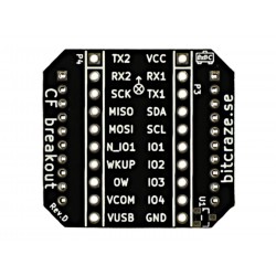
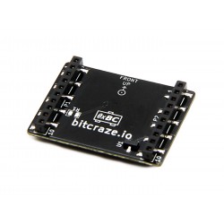
Crazyflie 2.0 - Breakout expansion board
4,50 €Add to cart -
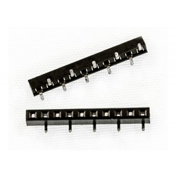
Crazyflie 2.0 - Female expansion...
2,00 €Add to cart -
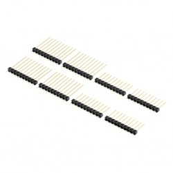
Crazyflie 2.0 - male expansion...
2,90 €Add to cart -
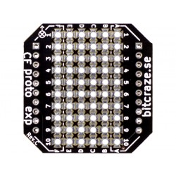
Crazyflie 2.0 - Prototyping expansion...
5,00 €Add to cart -
Crazyflie 2.0 Z-ranger deck board
25,00 €Add to cart -
Crazyflie 2.0: 4 x spare 7 mm motor...
5,50 €Add to cart -
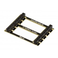
Crazyflie2.0 - Battery holder...
5,20 €Add to cart -
Digital Commom Button Module
3,99 €Add to cart -
Digital Commom Button Module V2.0...
5,99 €Add to cart -
Flow Breakout Board
45,00 €Add to cart -
KIT Workshop - Base level WITHOUT...
35,00 €Add to cart -
Kit Workshop- Basic level
69,60 €Add to cart -
LattePanda 2G/32BG kit
172,90 €Add to cart -

Pro Android Open Accessory...
36,00 €Add to cart -
Sensor Shield V5.0 -Arduino Compatible
15,99 €Add to cart -
Shield - Wireless Shield
15,90 €Add to cart -
Slave Serial Port Bluetooth Module Kit
34,50 €Add to cart -
Teensy 3.2 Kit
74,99 €Add to cart -
Teensy 3.2 With Pins
25,30 €Add to cart -
Teensy 3.2 Without Pins
22,30 €Add to cart -
TinkerKit - Basic Kit
79,90 €Add to cart -
TinkerKit - Starter Kit
79,90 €Add to cart -
Tinkerkit Dmx Master Shield
20,00 €Add to cart -
TinkerKit IR Remote Control
4,90 €Add to cart -
TinkerKit Mega Sensor Shield
14,60 €Add to cart -
TinkerKit Mosfet module
6,30 €Add to cart -
TinkerKit Sensor Shield V.2 MODULE
12,10 €Add to cart -
Touch Board
46,90 €Add to cart -
USB Host Android ADK Shield V2.3
16,90 €Add to cart -
Wire Male/Female 10 pcs
2,99 €Add to cart -
Wrobot Crash Sensor
3,99 €Add to cart -
Arduino Motor Shield Rev3
20,00 €Add to cart -
Arduino Self-Adhesive Breadboard -...
5,90 €Add to cart -
Arduino Self-Adhesive Breadboard -...
3,75 €Add to cart -
EEPROM Shield With 512K
16,09 €Add to cart -
Full Breadboard PCB Module
5,90 €Add to cart -
Gravity: 9 Pcs Sensor Set for Arduino
31,68 €Add to cart -
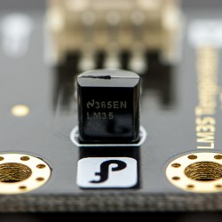
Gravity:Analog LM35 Linear...
5,18 €Add to cart -
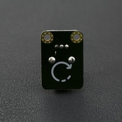
Gravity:Analog Rotation Sensor V2
4,03 €Add to cart -
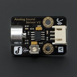
Gravity:Analog Sound Sensor
7,94 €Add to cart -
Gravity:DIGITAL IR Transmitter Module
5,18 €Add to cart -
IR Kit For Arduino
8,63 €Add to cart -
L293D
3,90 €Add to cart -

Making Things Talk 2nd Edition
28,00 €Add to cart -
Multi Rotary Sensor -Arduino Compatible
7,59 €Add to cart -
Reflectional Infrared Switch Sensor -...
4,15 €Add to cart -
Rotary Angle Sensor
3,59 €Add to cart -
Serial LCD-1602 Shield
22,90 €Add to cart -
Shield - Xbee
35,00 €Add to cart -
Small DC motor
2,90 €Add to cart -
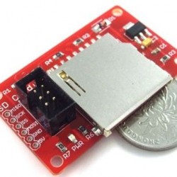
SPI SD Memory Shield
11,39 €Add to cart -
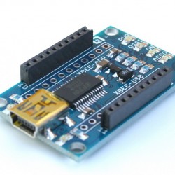
XBee USB Adapter
14,89 €Add to cart -
Display color TFT 320x240
9,89 €Add to cart -
Display color TFT 320x240 Touchscreen...
13,90 €Add to cart -
LumaxNET ILDA
289,00 €Add to cart -

LumaxNET ILDA
215,00 €Add to cart -
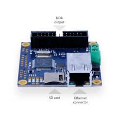
Moncha lite laser controller
285,00 €Add to cart -
Wireless controller HTC Vive
155,90 €Add to cart -

RC 2.4G Wireless Air Mouse & Keyboard
28,69 €Add to cart
CORZOTECH - EASY LIFE FOR INTERACTION