No products
Product successfully added to your shopping cart
There are 0 items in your cart. There is 1 item in your cart.
Adafruit
Top sellers
-

Services
1,00 € -

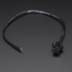
4 Pin Dual-female...
0,85 € -

-

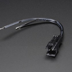
6 Pin Dual-female...
1,89 €
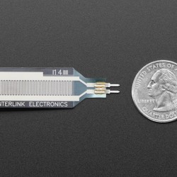
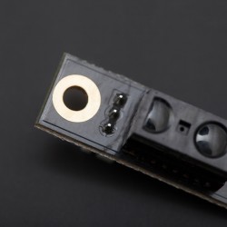
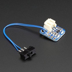
 View larger The picture may differ from the original
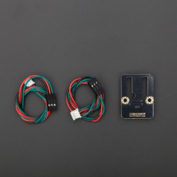

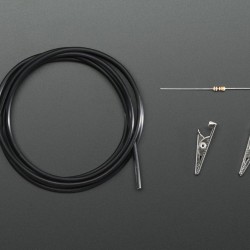
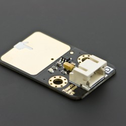
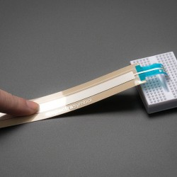
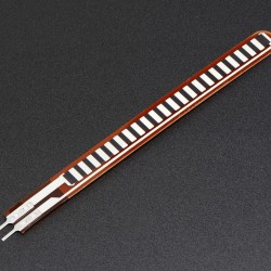
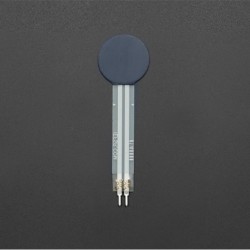
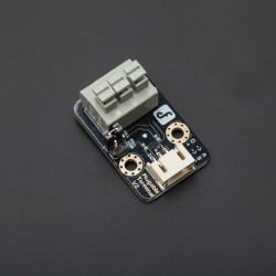
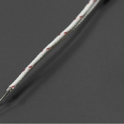
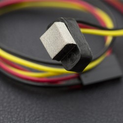
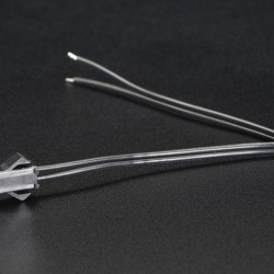
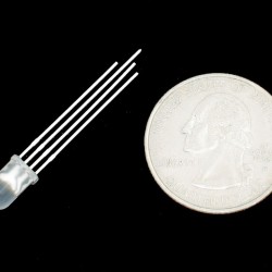
12" Chemical eTape Liquid Level Sensor with Teflon Jacket
AC01786
New

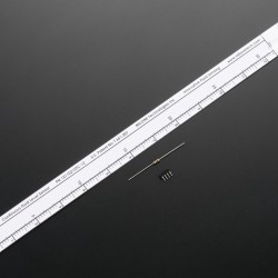
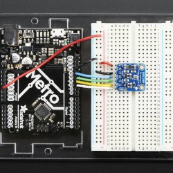
The Chemical eTape Liquid Level Sensor is a solid-state sensor with a resistive output that varies with the level of the fluid. It does away with clunky mechanical floats, and easily interfaces with electronic control systems. What separates this from our other eTape Liquid Sensor is the Teflon (FEP) jacket that is rated for use in chemical, petroleum, and food safe applications
The eTape sensor's envelope is compressed by the hydrostatic pressure of the fluid in which it is immersed. This results in a change in resistance that corresponds to the distance from the top of the sensor to the surface of the fluid. The sensor's resistive output is inversely proportional to the height of the liquid: the lower the liquid level, the higher the output resistance; the higher the liquid level, the lower the output resistance.
This is a very unique sensor, we haven't seen anything else that is affordable and accurate for measuring liquid level. This particular sensor is the 12" model, we also include a 4-pin connector and 560 ohm resistor. The connector is so you don't have to solder directly to the delicate pins: instead, just solder to the connector and plug it onto the sensor.
Since the sensor is resistive, it is easy to read it using a microcontroller/Arduino ADC pin. Check the tutorials tab for a quick-start pointer.
Dimensions:
- 305mm x 25mm / 12" x 1"
- Weight: 5g
- Sensor Length: 361mm / 14.2"
- Thickness: 0.38mm / 0.02"
- Tech Specs:
- Sensor Output: 400-2000Ω ±20%
- Ref. Resistance: 2000Ω ±20%
- Actuation Depth: Nominal 25.4mm / 1"
- Resistance Gradient: 60Ω/cm / 150Ω /inch
- Power Rating: 0.5 Watts
- Temperature Range: 15°F - 150°F / -9°C - 65°C
We don't have a detailed tutorial for this sensor but it acts very much like a thermistor so we suggest checking out that tutorial for background, and then following these instructions:
Connect pin #2 of the sensor to ground, then pin #3 to a 560 ohm resistor. The other side of the 560 ohm resistor to VCC (3.3V or 5V for example) to create a resistor divider. The ADC pin connects to the point between the resistor and sensor.
// the value of the 'other' resistor
#define SERIESRESISTOR 560

// What pin to connect the sensor to
#define SENSORPIN A0

void setup(void) {
  Serial.begin(9600);
}

void loop(void) {
  float reading;

  reading = analogRead(SENSORPIN);

  Serial.print("Analog reading ");
  Serial.println(reading);

  // convert the value to resistance
  reading = (1023 / reading)  - 1;
  reading = SERIESRESISTOR / reading;
  Serial.print("Sensor resistance ");
  Serial.println(reading);

  delay(1000);
}
Tags

Related Products
-
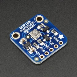
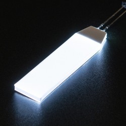
Barometric...
9,60 €Add to cart -

12" eTape Liquid Level Sensor + extras
39,95 €Add to cart -
12" Standard eTape Liquid Level...
56,99 €Add to cart -
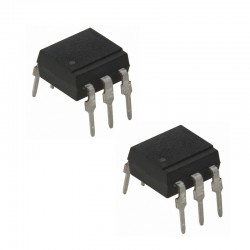
4N35 Optocoupler
0,90 €Add to cart -
Adafruit BME280 I2C or SPI...
21,90 €Add to cart -
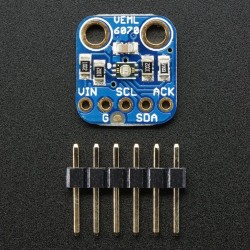
Adafruit VEML6070 UV Index Sensor...
6,89 €Add to cart -
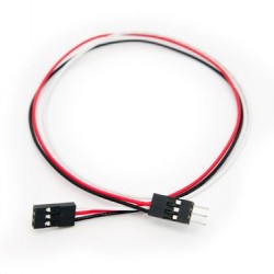
Arduino Sensor Extension Cable-30cm
1,80 €Add to cart -
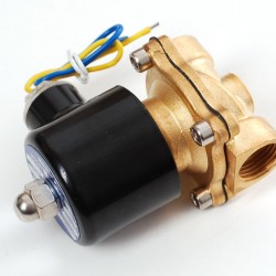
Brass Liquid Solenoid Valve
28,70 €Add to cart -
Conductive Rubber Cord Stretch Sensor...
9,00 €Add to cart -
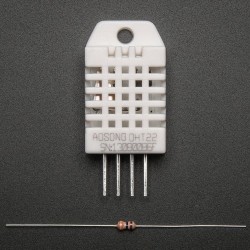
DHT22 temperature-humidity sensor +...
11,45 €Add to cart -
Expansion Pack
53,10 €Add to cart -
Extra-long force-sensitive resistor...
20,69 €Add to cart -
FLORA 9-DOF...
22,99 €Add to cart -
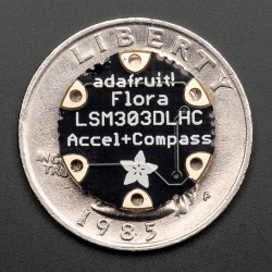
FLORA Accelerometer/Compass Sensor
17,20 €Add to cart -
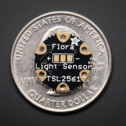
Flora Lux Sensor - TSL2561 Light...
9,15 €Add to cart -
Flora UV Index Sensor
10,30 €Add to cart -
Gravity: Digital Capacitive Touch Sensor
6,79 €Add to cart -
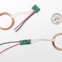
Inductive Charging Set
11,45 €Add to cart -
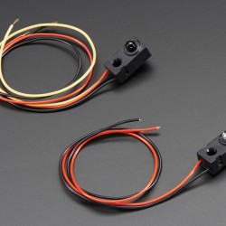
IR Break Beam Sensor
7,95 €Add to cart -
Linear SoftPot (Ribbon Sensor) - 100mm
8,23 €Add to cart -
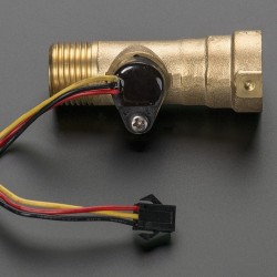
Liquid Flow Meter
28,70 €Add to cart -
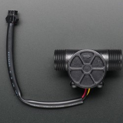
Liquid Flow Meter
11,45 €Add to cart -

Long Flex/Bend sensor
14,98 €Add to cart -
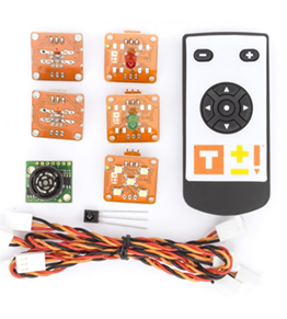
Microsoft Azure IoT Starter Kit w
49,50 €Add to cart -
Mini Motor Speed Sensor -B
6,99 €Add to cart -
PI CAP
32,50 €Add to cart -
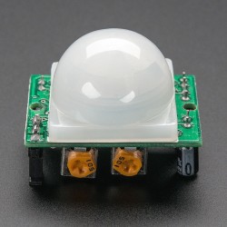
PIR (motion) sensor
8,90 €Add to cart -
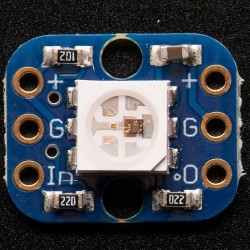
Pixie - 3W Chainable Smart LED Pixel
17,20 €Add to cart -
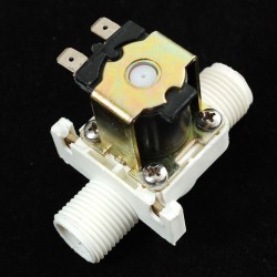
Plastic Water Solenoid Valve
7,10 €Add to cart -

Pressure-Sensitive Conductive Sheet...
4,50 €Add to cart -
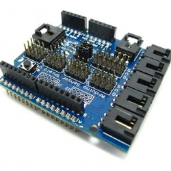
Sensor Shield V5.0 -Arduino Compatible
15,99 €Add to cart -
Short Flex/Bend Sensor
6,67 €Add to cart -

Standalone 5-Pad Capacitive Touch...
8,65 €Add to cart -
TinkerKit - Basic Kit
79,90 €Add to cart -
TinkerKit Mega Sensor Shield
14,60 €Add to cart -
TinkerKit Sensor Shield V.2 MODULE
12,10 €Add to cart -
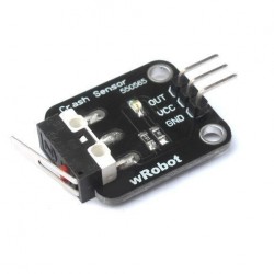
Wrobot Crash Sensor
3,99 €Add to cart -
Z-Wave.Me Raspberry Security Bundle,...
132,90 €Add to cart -
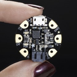
Adafruit GEMMA v2
11,45 €Add to cart -
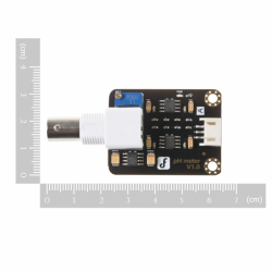
Analog pH Meter Kit
33,93 €Add to cart -
CO2 Sensor (Arduino compatible)
64,46 €Add to cart -
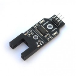
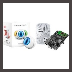
Digital Infrared Motion Sensor
6,44 €Add to cart -
Digital Output-Port Shield V2.0
10,39 €Add to cart -
Force Sensitive Resistor 0.5
7,94 €Add to cart -
Gravity: Digital Piezo Disk Vibration...
5,18 €Add to cart -
Gravity: DS18B20 Temperature Sensor...
4,60 €Add to cart -
Gravity:Analog Grayscale Sensor V2
5,18 €Add to cart -
Gravity:DHT11 Temperature and...
5,98 €Add to cart -
Gravity:Digital Infrared Distance...
11,27 €Add to cart -
Gravity:SHT1x Humidity and...
24,21 €Add to cart -
Gravity:Terminal Sensor Adapter V2.0
2,82 €Add to cart -
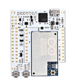
Huzzah! Adafruit.io Internet of...
43,65 €Add to cart -
K Type Thermocouple
6,89 €Add to cart -
L293D
3,90 €Add to cart -
LilyPad Light Sensor
9,14 €Add to cart -
Mini Touch Kit
7,94 €Add to cart -
Needle set - 3/9 sizes
2,25 €Add to cart -
Non-contact Liquid Level Switch
16,56 €Add to cart -

Prop Shield With Motion Sensors
22,49 €Add to cart -
Prop Shield, Low Cost (no Motion...
9,69 €Add to cart -
Pulse Sensor Amped
28,75 €Add to cart -
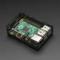
Raspberry Pi Model B+ / Pi 2 Case Lid
3,45 €Add to cart -
Reflectional Infrared Switch Sensor -...
4,15 €Add to cart -
Rotary Angle Sensor
3,59 €Add to cart -
Peristaltic Liquid Pump with Silicone...
26,50 €Add to cart -

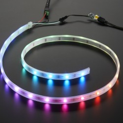
Digital LED Strip APA102-144 LED/m -...
50,00 €Add to cart -

NeoPixel NeoMatrix 8x8
33,50 €Add to cart -
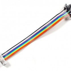
10-pin IDC Socket Rainbow Breakout Cable
3,40 €Add to cart -
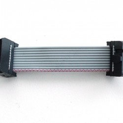
10-pin Socket/Socket IDC cable
1,57 €Add to cart -
10-pin Socket/Socket IDC cable - 6"
2,07 €Add to cart -
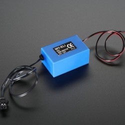
12V EL wire/tape inverter
5,99 €Add to cart -
13.56MHz RFID/NFC Sticker - 1KB
2,89 €Add to cart -

13.56MHz RFID/NFC White Tag - 1KB
2,89 €Add to cart -
2-pin JST SM Plug + Receptacle Cable Set
0,70 €Add to cart -
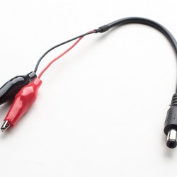
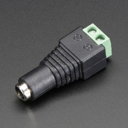
2.1mm DC Barrel Plug to Alligator Clips
2,25 €Add to cart -
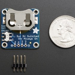
20mm Coin Cell Breakout w/On-Off...
8,10 €Add to cart -
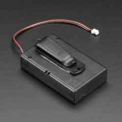
3 x AA Battery Holder with On/Off...
3,55 €Add to cart -
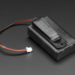
3 x AAA Battery Holder with On/Off...
3,49 €Add to cart -
3M Z-Axis Conductive Tape 9703
6,30 €Add to cart -
3x4 Right Angle Male Header - 4 pack
3,50 €Add to cart -
8-Channel PWM or Servo FeatherWing...
11,69 €Add to cart -
Adafruit 16x8 LED Matrix Driver Backpack
6,99 €Add to cart -
Adafruit 6-pin AVR ISP Breadboard...
1,65 €Add to cart -
Adafruit 7-Segment LED Matrix Backpack
7,25 €Add to cart -
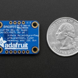
Adafruit 9-DOF Absolute Orientation...
33,50 €Add to cart -
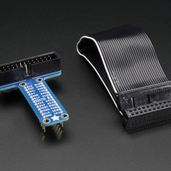
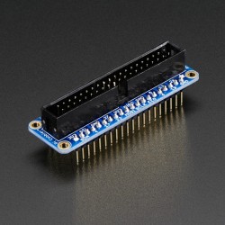
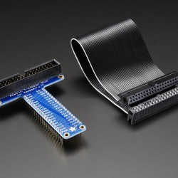
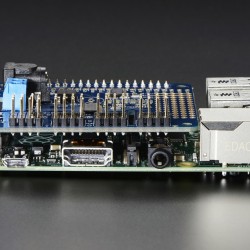
Adafruit Assembled Pi T-Cobbler...
6,95 €Add to cart -
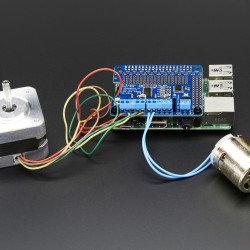
Adafruit DC & Stepper Motor HAT for...
25,89 €Add to cart -
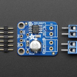
Adafruit DRV8871 DC Motor Driver...
8,90 €Add to cart -
Adafruit Feather HUZZAH with ESP8266...
14,40 €Add to cart -
Adafruit Feather M0 Adalogger
22,30 €Add to cart -
Adafruit Feather M0 RFM69 Packet Radio
25,99 €Add to cart -
Adafruit Half-size Perma
5,10 €Add to cart -
Adafruit HUZZAH ESP8266 Breakout
11,45 €Add to cart -
Adafruit LED Sequins
4,55 €Add to cart -
Adafruit Micro Lipo w/MicroUSB Jack -...
8,15 €Add to cart -
Adafruit Motor/Stepper/Servo Shield...
22,94 €Add to cart -
Adafruit NeoPixel LED Strip Starter Pack
28,70 €Add to cart -
Adafruit PN532 NFC/RFID Controller...
45,99 €Add to cart -
Adafruit PowerBoost 500 Shield
22,99 €Add to cart -
Adafruit Pro Trinket LiIon/LiPoly...
5,99 €Add to cart -
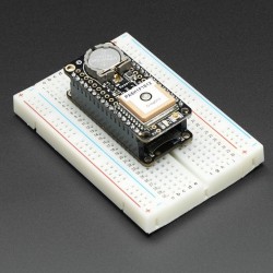
Adafruit Ultimate GPS FeatherWing
43,50 €Add to cart -
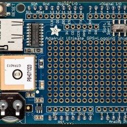
Adafruit Ultimate GPS Logger Shield
49,90 €Add to cart -
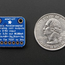
ADXL335 - 5V ready triple-axis...
17,20 €Add to cart -
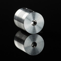
Aluminum Flex Shaft Coupler
5,70 €Add to cart -
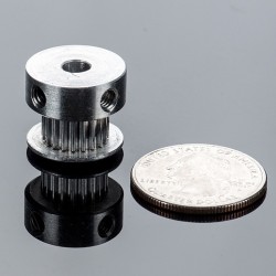
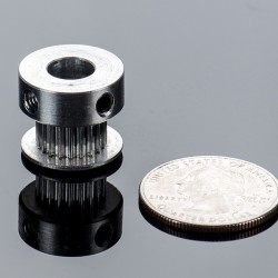
Aluminum GT2 Timing Pulley
9,15 €Add to cart -
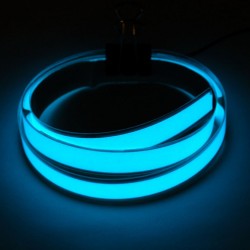
Aqua Electroluminescent (EL) Tape Strip
11,99 €Add to cart -
Assembled Drawdio fun pack - v1.1
25,87 €Add to cart -
Assembled Pi Cobbler Plus - Breakout...
6,95 €Add to cart -
Assembled Pi T-Cobbler Plus - GPIO...
6,99 €Add to cart -
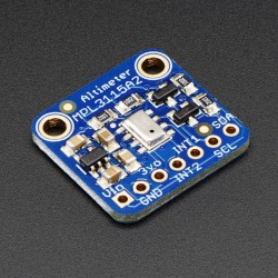
Barometric...
9,60 €Add to cart -
Bone Conductor Transducer with Wires
10,30 €Add to cart -
Breadboard-friendly RGB Smart NeoPixel
9,15 €Add to cart -
Circular Soft Potentiometer
9,15 €Add to cart -

Conductive Fiber
4,20 €Add to cart -

Conductive thread ribbon cable - Black
6,19 €Add to cart -
Controllable Four Outlet Power Relay...
22,00 €Add to cart -
Copper Foil Tape with Conductive...
6,85 €Add to cart -
Copper Foil Tape wth Conductive...
25,95 €Add to cart -
DE-15 (DB-15) Female Socket to...
5,19 €Add to cart -
DE-15 (DB-15) Male Plug to Terminal...
5,19 €Add to cart -
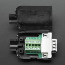
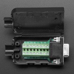
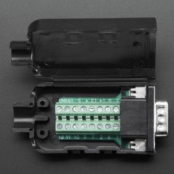
DE-9 (DB-9) Male Plug to Terminal...
3,49 €Add to cart -
Diffused RGB (tri-color) LED
2,60 €Add to cart -
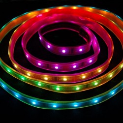
Digital RGB LED Weatherproof Strip-...
34,44 €Add to cart -
Easy Connector female For LED Strip...
1,59 €Add to cart -
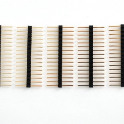
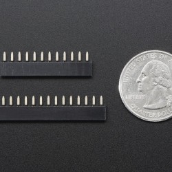
Extra-long break-away 0.1" 16-pin...
3,45 €Add to cart -
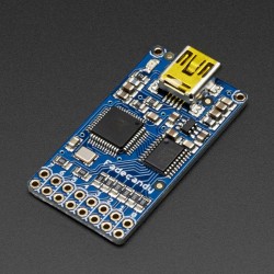
FadeCandy - Dithering USB
28,70 €Add to cart -
Fast Vibration Sensor Switch
1,10 €Add to cart -
Feather Header Kit
1,05 €Add to cart -
Feather Stacking Headers
1,45 €Add to cart -

Flex PCB Material - Pyralux - 6" by...
12,50 €Add to cart -
FLORA - Wearable electronic platform
14,60 €Add to cart -
Flora RGB Smart NeoPixel version 2
40,20 €Add to cart -
Flora RGB Smart NeoPixel version 2
9,15 €Add to cart -
Flora Sewable 3-Pin JST Wiring Adapter
2,99 €Add to cart -
GPIO Header for Raspberry Pi
2,00 €Add to cart -
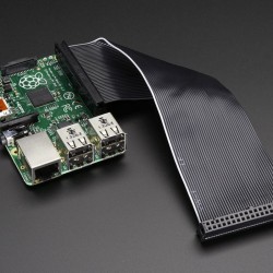
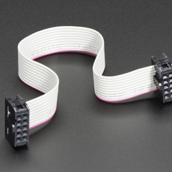
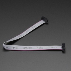
GPIO Ribbon Cable for Raspberry Pi...
2,95 €Add to cart -
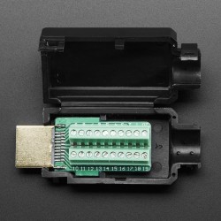
HDMI Plug to Terminal Block Breakout
8,65 €Add to cart -
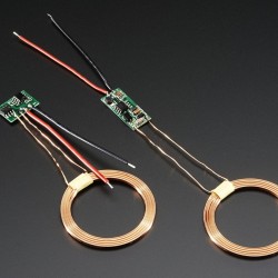
Inductive Charging Set
11,45 €Add to cart -

ITO (Indium Tin Oxide) Coated Glass
6,85 €Add to cart -

Keyfob 4-Button RF Remote Control
6,25 €Add to cart -

Knit Conductive Fabric
11,45 €Add to cart -

Knit Jersey Conductive Fabric
10,30 €Add to cart -
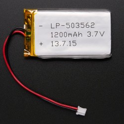
Lithium Ion Polymer Battery - 3.7v...
9,90 €Add to cart -
Lithium Ion Polymer Battery - 3.7v...
15,10 €Add to cart -
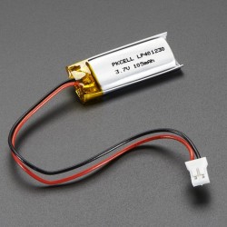
Lithium Ion Polymer Battery 3.7v 100mAh
5,99 €Add to cart -
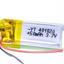
Lithium Ion Polymer Battery 3.7v 50mAh
2,65 €Add to cart -
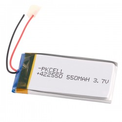
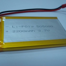
Lithium Ion Polymer Battery 3.7v 550mAh
7,90 €Add to cart -
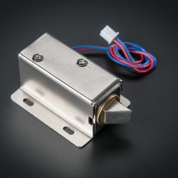
Lock-style Solenoid - 12VDC
14,99 €Add to cart -
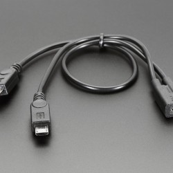
Micro B USB 2-Way Y Splitter Cable
3,49 €Add to cart -
Microsoft Azure IoT Starter Kit w
110,70 €Add to cart -
Microsoft IoT Pack for Raspberry Pi 3 -
119,70 €Add to cart -
Mini Hand from Hobby Creek with Two Arms
34,50 €Add to cart -

Miniature Slip Ring
22,90 €Add to cart -
Miniature Slip Ring
16,20 €Add to cart -
Monochrome 128x32 I2C OLED graphic...
20,15 €Add to cart -
NeoPixel 1/4 60 Ring - WS2812 5050...
11,45 €Add to cart -
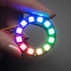
NeoPixel Ring - 12 x WS2812 5050 RGB...
8,50 €Add to cart -
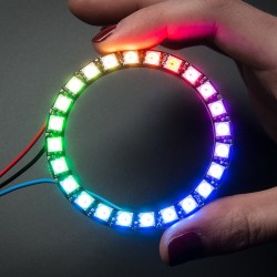
NeoPixel Ring - 24 x WS2812 5050 RGB...
22,94 €Add to cart -

NeoPixel Shield for Arduino - 40 RGB...
32,14 €Add to cart -
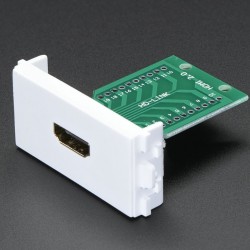
Panel Mount HDMI Socket Breakout
4,05 €Add to cart -
Pi Model B+ / Pi 2 Case Base
4,99 €Add to cart -
Pomona Female 0.1" Socket to Banana Plug
9,29 €Add to cart -

Precision Straight Tweezers
9,95 €Add to cart -
Professional Non-Slip Magnetic...
24,95 €Add to cart -
RFID RFID/NFC S50 Card Reader
37,90 €Add to cart -
Round Force-Sensitive Resistor (FSR)
7,24 €Add to cart -
Shield stacking headers for Arduino...
2,25 €Add to cart -
Silicone Clips and Screws for...
2,25 €Add to cart -
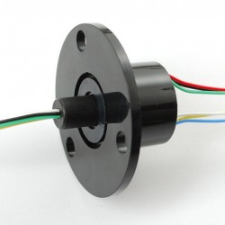
Slip Ring with Flange
13,90 €Add to cart -
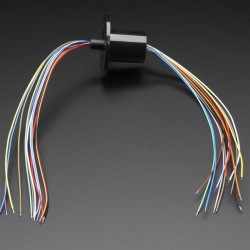
Slip Ring with Flange
18,00 €Add to cart -
Soft Potentiometer Kit from Plug&Wear
10,49 €Add to cart -
Stacking Header for Pi A+/B+/Pi 2
3,40 €Add to cart -
Stacking Header for Raspberry Pi
2,25 €Add to cart -
Stainless Medium Conductive Thread
8,00 €Add to cart -

Stainless Steel Conductive Ribbon...
26,99 €Add to cart -
Stainless Thin Conductive Thread
7,15 €Add to cart -
Sugru - Black and White Pack
19,99 €Add to cart -
Universal Qi Wireless Charging Module
32,10 €Add to cart -
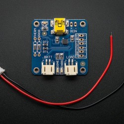
USB LiIon/LiPoly charger - v1.2
14,99 €Add to cart -
White LED Backlight Module
2,25 €Add to cart -

Woven Conductive Fabric
5,70 €Add to cart -
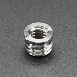
1/4" to 1/4" Screw Adapter
1,75 €Add to cart -
10-pin 2x5 Socket-Socket 1.27mm IDC...
3,40 €Add to cart -

13.56MHz RFID/NFC Bracelet - 1KB
4,69 €Add to cart -
16-Channel PWM / Servo HAT for...
20,15 €Add to cart -
2-pin JST SM In-line power wire...
0,89 €Add to cart -
2-pin JST SM In-line power wire...
0,89 €Add to cart -
2.1mm female/male barrel jack...
3,40 €Add to cart -

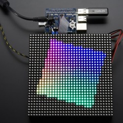
32x32 RGB LED Matrix Panel - 4mm Pitch
57,99 €Add to cart -
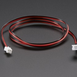
4-pin JST SM Plug + Receptacle Cable Set
1,75 €Add to cart -
4-Way 2.1mm DC Barrel Jack Splitter
5,70 €Add to cart -

6-pin Socket/Socket IDC cable - 6"
2,30 €Add to cart -
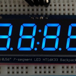
Adafruit 0.56" 4-Digit 7
13,75 €Add to cart -
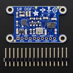
Adafruit 10-DOF IMU Breakout
34,45 €Add to cart -

Adafruit Capacitive Touch HAT for...
17,20 €Add to cart -
Adafruit RGB Matrix HAT + RTC for...
28,69 €Add to cart -
Adafruit Triple-Axis Accelerometer
9,15 €Add to cart -
Aluminum Flex Shaft Coupler
5,70 €Add to cart -
Aluminum GT2 Timing Pulley
13,75 €Add to cart -
Aluminum GT2 Timing Pulley
13,75 €Add to cart -
Aluminum GT2 Timing Pulley
9,15 €Add to cart -
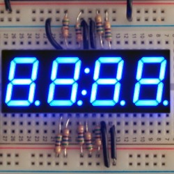
Blue 7-segment clock display
6,85 €Add to cart -
Camera and Tripod 3/8" to 1/4"...
1,75 €Add to cart -
Diffused 5mm Slow Fade Flashing RGB LED
5,70 €Add to cart -
GPIO Header for Raspberry Pi A+/B+/Pi 2
1,75 €Add to cart -
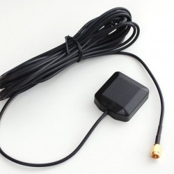
GPS Antenna - External Active Antenna
14,90 €Add to cart -
High Brightness Red...
13,80 €Add to cart -
In-line power switch for 2.1mm barrel...
2,90 €Add to cart -

ITO (Indium Tin Oxide) Coated PET...
11,45 €Add to cart -
JST-PH Battery Extension Cable - 500mm
2,95 €Add to cart -
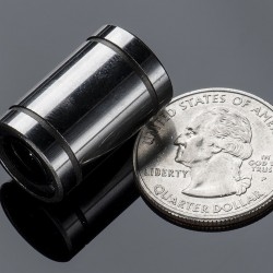
Linear Ball Bearing
3,40 €Add to cart -
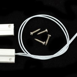
Magnetic contact switch (door sensor)
4,55 €Add to cart -

Medium 16x32 RGB LED matrix panel...
29,99 €Add to cart -
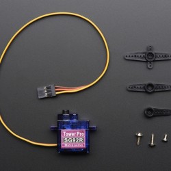
Micro servo
6,85 €Add to cart -
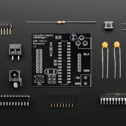
Nootropic RGB Matrix Backpack
22,99 €Add to cart -
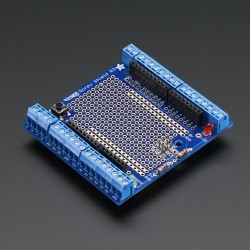
Proto-Screwshield (Wingshield) R3 Kit...
17,19 €Add to cart -
Raspberry Pi Model A+ Case Lid
2,30 €Add to cart -
Raspberry Pi Model B+ / Pi 2 Case Lid
3,45 €Add to cart -
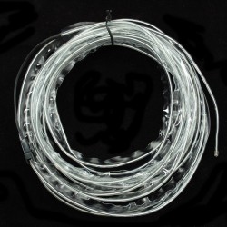
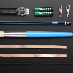
Sewable Electroluminscent (EL) Wire...
22,99 €Add to cart -
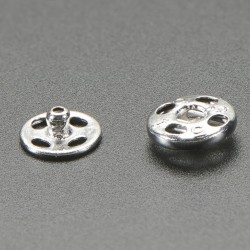
Sewable Snaps - 5mm Diameter
4,55 €Add to cart -
Short Feather Headers Kit
1,75 €Add to cart -
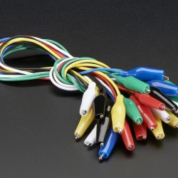
Small Alligator Clip Test Lead
4,55 €Add to cart -
Stainless Thin Conductive Yarn /...
5,19 €Add to cart -
Super Bright Blue 5mm LED
9,20 €Add to cart -
Super Bright White 5mm LED
8,00 €Add to cart -
Universal Qi Wireless Receiver Module
17,20 €Add to cart
CORZOTECH - EASY LIFE FOR INTERACTION