Ningún producto
Producto añadido correctamente a su carrito de la compra
Hay 0 artículos en su carrito. Hay 1 artículo en su cesta.
Módulos
¡Lo más vendido!
-

Servicios
1,00 € -

4 Pin Dual-female...
0,85 € -

-

6 Pin Dual-female...
1,89 €
 Ver más grande La imagen puede diferir del original
TinkerKit Gyroscope 2 Axis sensitivity 1X
T000060
Nuevo
Este producto ya no está disponible

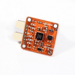
Un giroscopio es un dispositivo que mide la orientación. Es muy común en la electrónica de consumo, así como en los dispositivos electrónicos portátiles y también en los controladores de videojuegos. El giroscopio detecta el movimiento y la rotación.
Salida: Este módulo genera una señal de salidas desde 0V hasta 5V en una de las dos patillas cuando el ángulo se cambia (por ej. si se mueve). El nivel es de aproximadamente 2,5 V cuando no hay un cambio de ángulo en el eje X o Y. Cuando tu conectas este módulo a la entrada de un Arduino usando el TinkerKit Shield, puedes esperar a leer los valores entre 0 y 1023 cambiando el ángulo del módulo.
Descripción del Módulo: en la placa hay un LED verde, lo cual indica que el módulo está correctamente alimentado. El módulo se basa en la LPR5150AL de ST Microelectronics, y es un giroscopio de dos ejes. La versión de este módulo devuelve el pin del chip amplificado 4 veces. Para más información sobre esto, por favor eche un vistazo al datasheet (hoja de datos).
Este módulo es un SENSOR. Cada conector es un OUTPUT que debe estar conectado a uno de los INPUT conectores de la TinkerKit Shield.
/* TinkerKit! Gyroscope [T000060-64]
*
* This sketch shows how to read this 2-axis gyroscope,
* turning in a given angular velocity and then converting it
* in the simplest way in an angular position (/inclination).
*
* Connect: the X-axis to the Analog Input Pin 0 (I0)
* the Y-axis to the Analog Input Pin 1 (I1)
* Optional: connect a servo to Analog Output Pin 9 (O2)
*
* created by Federico Vanzati / f.vanzati@arduino.cc
* in September 2011
*
* inspired from www.arduino.cc/playground/Main/Gyro
* by eric barch / ericbarch.com
*/
#include <Servo.h>
// Pin used in this example
#define SERVO 9
#define X_GYRO 0
#define Y_GYRO 1
#define ADCresolution 4.89f // = 5000mV/1023counts: Arduino analog pins resolution expressed in mV/count
#define Sensitivity 0.67f // [mV/dps] sensitivity of the sensor, took from datasheet (4x output mode)
// Conversion coefficient, we do here because is a constant! so we'll not do the calculation every loop
#define K ADCresolution/Sensitivity // the constant!
#define nrSamples 6 // Number of samples that we take for each measure
Servo myservo; // create servo object to control a servo
// a maximum of eight servo objects can be created
// Timing variables
unsigned long time, sampleTime = 12;
unsigned long printTime = 0, serialRefresh_time = 500;
float deltaT = (float)sampleTime*nrSamples/1000;
//Gyroscope variables
int roll_zeroVoltage, pitch_zeroVoltage;
int roll_rawADC[nrSamples], pitch_rawADC[nrSamples]; // store 3 values...just to avverage
float roll_rate, pitch_rate; //
float roll_angle = 0, pitch_angle = 0;
int c=0; // just a counter to count the samples
int pos; // variable to store the servo position
void setup()
{
delay(1000);
myservo.attach(SERVO); // attaches the servo on pin 9 to the servo object
myservo.write(pos);
Serial.begin(57600);
Serial.print("TinkerKit! Gyroscope [T000062] Test Examplenn");
int correctionY=0, correctionX=0;
for (int i=0; i<50; i++)
{
correctionY += analogRead(Y_GYRO);
correctionX += analogRead(X_GYRO);
delay(20);
}
roll_zeroVoltage = correctionY/50;
pitch_zeroVoltage = correctionX/50;
Serial.print(roll_zeroVoltage);
Serial.print(" ");
Serial.println(pitch_zeroVoltage);
time = millis();
}
void loop()
{
// Every 40ms take a sample from gyro
if(millis() - time > sampleTime)
{
time = millis();
roll_rawADC[c] = analogRead(Y_GYRO);
pitch_rawADC[c] = analogRead(X_GYRO);
c++;
}
if(c==nrSamples) // Well, we have 3 samples
{
// Transform the raw data into an angular velocity
roll_rate = (filterGyro(roll_rawADC) - roll_zeroVoltage) * K;
pitch_rate = (filterGyro(pitch_rawADC) - pitch_zeroVoltage)* K;
// Integrate the angular veloity to obtain angular position (or inclination)
// Using the trapeziod method for numerical integration
// sampleTime*nrSamples
// The variable that take mind of the integration time is deltaT = --------------------
// 1000
// - we multiply for nrSamples because
// - divide for 1000 because angular velocity is expessed in seconds,
// but sampleTime is expressed in milliseconds
roll_angle += roll_rate*deltaT/2;
pitch_angle += pitch_rate*deltaT/2;
//Keep our angle between 0-359 degrees
if (roll_angle < 0)
roll_angle += 360;
else if (roll_angle > 359)
roll_angle -= 360;
if (pitch_angle < 0)
pitch_angle += 360;
else if (pitch_angle > 359)
pitch_angle -= 360;
// Now we control the servo: home position is setted in the center at 90 degrees
if(roll_angle >= 0 && roll_angle <= 90) // counterclockwise rotation of the gyro...
pos = 90 + (int)roll_angle; // ...produces rotation from 90 to 180 deg on servo
if(roll_angle >= 270) // clockwike rotation of the gyro...
pos = (int)roll_angle - 270; // ...produces rotation from 90 to 0 deg on servo
myservo.write(pos); // send the position to servo
if(millis() - printTime > serialRefresh_time)
{
printTime = millis();
Serial.print("Roll speed: "); Serial.print((int)roll_rate);
Serial.print("t Angle: "); Serial.print((int)roll_angle);
Serial.print("t Pitch speed: "); Serial.print((int)pitch_rate);
Serial.print("t Angle: "); Serial.println((int)pitch_angle);
Serial.print("Servo: "); Serial.println(pos);
}
c=0; // reset the counter
}
}
int filterGyro(int buffer[])
{
int mean=0;
for(byte i=0; i<nrSamples; i++)
mean += buffer[i];
mean /= nrSamples;
return mean;
}

CORZOTECH - EASY LIFE FOR INTERACTION