No products
Product successfully added to your shopping cart
There are 0 items in your cart. There is 1 item in your cart.
Modules
Top sellers
-

Services
1,00 € -

4 Pin Dual-female...
0,85 € -

-

6 Pin Dual-female...
1,89 €
 View larger The picture may differ from the original
TinkerKit Gyroscope 2 Axis sensitivity 1X
T000060
New
This product is no longer in stock

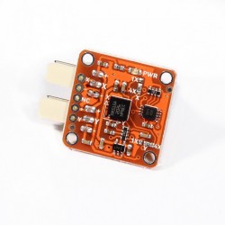
A gyroscope is a device that measures orientation. It is very common in consumer electronics such as portable electronic devices and video game controllers to detect movement and rotation.
Output: This module outputs 0V to 5V on one of its two signal pins when its angle is changed (e.g. is moved). The value is approximately 2.5V when there is no angle change in the X or Y axis. When you connect this module to the input on an Arduino using the TinkerKit Shield, you can expect to read values between 0 to 1023 while changing the angle of the module.
Module description: on the board you'll find a green LED that signals that the module is correctly powered. The module is based on the LPR5150AL by ST Microelectronics, and is a two-axis gyroscope. This version of the module outputs the 1X pins on the chip. For more information about this please have a look at the datasheet. This module is a SENSOR. Each connector is an OUTPUT which must be connected to one of the INPUT connectors on the TinkerKit Shield.
Code Example
/* TinkerKit! Gyroscope [T000060-64]
*
* This sketch shows how to read this 2-axis gyroscope,
* turning in a given angular velocity and then converting it
* in the simplest way in an angular position (/inclination).
*
* Connect: the X-axis to the Analog Input Pin 0 (I0)
* the Y-axis to the Analog Input Pin 1 (I1)
* Optional: connect a servo to Analog Output Pin 9 (O2)
*
* created by Federico Vanzati / f.vanzati@arduino.cc
* in September 2011
*
* inspired from www.arduino.cc/playground/Main/Gyro
* by eric barch / ericbarch.com
*/
#include <Servo.h>
// Pin used in this example
#define SERVO 9
#define X_GYRO 0
#define Y_GYRO 1
#define ADCresolution 4.89f // = 5000mV/1023counts: Arduino analog pins resolution expressed in mV/count
#define Sensitivity 0.67f // [mV/dps] sensitivity of the sensor, took from datasheet (4x output mode)
// Conversion coefficient, we do here because is a constant! so we'll not do the calculation every loop
#define K ADCresolution/Sensitivity // the constant!
#define nrSamples 6 // Number of samples that we take for each measure
Servo myservo; // create servo object to control a servo
// a maximum of eight servo objects can be created
// Timing variables
unsigned long time, sampleTime = 12;
unsigned long printTime = 0, serialRefresh_time = 500;
float deltaT = (float)sampleTime*nrSamples/1000;
//Gyroscope variables
int roll_zeroVoltage, pitch_zeroVoltage;
int roll_rawADC[nrSamples], pitch_rawADC[nrSamples]; // store 3 values...just to avverage
float roll_rate, pitch_rate; //
float roll_angle = 0, pitch_angle = 0;
int c=0; // just a counter to count the samples
int pos; // variable to store the servo position
void setup()
{
delay(1000);
myservo.attach(SERVO); // attaches the servo on pin 9 to the servo object
myservo.write(pos);
Serial.begin(57600);
Serial.print("TinkerKit! Gyroscope [T000062] Test Examplenn");
int correctionY=0, correctionX=0;
for (int i=0; i<50; i++)
{
correctionY += analogRead(Y_GYRO);
correctionX += analogRead(X_GYRO);
delay(20);
}
roll_zeroVoltage = correctionY/50;
pitch_zeroVoltage = correctionX/50;
Serial.print(roll_zeroVoltage);
Serial.print(" ");
Serial.println(pitch_zeroVoltage);
time = millis();
}
void loop()
{
// Every 40ms take a sample from gyro
if(millis() - time > sampleTime)
{
time = millis();
roll_rawADC[c] = analogRead(Y_GYRO);
pitch_rawADC[c] = analogRead(X_GYRO);
c++;
}
if(c==nrSamples) // Well, we have 3 samples
{
// Transform the raw data into an angular velocity
roll_rate = (filterGyro(roll_rawADC) - roll_zeroVoltage) * K;
pitch_rate = (filterGyro(pitch_rawADC) - pitch_zeroVoltage)* K;
// Integrate the angular veloity to obtain angular position (or inclination)
// Using the trapeziod method for numerical integration
// sampleTime*nrSamples
// The variable that take mind of the integration time is deltaT = --------------------
// 1000
// - we multiply for nrSamples because
// - divide for 1000 because angular velocity is expessed in seconds,
// but sampleTime is expressed in milliseconds
roll_angle += roll_rate*deltaT/2;
pitch_angle += pitch_rate*deltaT/2;
//Keep our angle between 0-359 degrees
if (roll_angle < 0)
roll_angle += 360;
else if (roll_angle > 359)
roll_angle -= 360;
if (pitch_angle < 0)
pitch_angle += 360;
else if (pitch_angle > 359)
pitch_angle -= 360;
// Now we control the servo: home position is setted in the center at 90 degrees
if(roll_angle >= 0 && roll_angle <= 90) // counterclockwise rotation of the gyro...
pos = 90 + (int)roll_angle; // ...produces rotation from 90 to 180 deg on servo
if(roll_angle >= 270) // clockwike rotation of the gyro...
pos = (int)roll_angle - 270; // ...produces rotation from 90 to 0 deg on servo
myservo.write(pos); // send the position to servo
if(millis() - printTime > serialRefresh_time)
{
printTime = millis();
Serial.print("Roll speed: "); Serial.print((int)roll_rate);
Serial.print("t Angle: "); Serial.print((int)roll_angle);
Serial.print("t Pitch speed: "); Serial.print((int)pitch_rate);
Serial.print("t Angle: "); Serial.println((int)pitch_angle);
Serial.print("Servo: "); Serial.println(pos);
}
c=0; // reset the counter
}
}
int filterGyro(int buffer[])
{
int mean=0;
for(byte i=0; i<nrSamples; i++)
mean += buffer[i];
mean /= nrSamples;
return mean;
}

CORZOTECH - EASY LIFE FOR INTERACTION