Ningún producto
Producto añadido correctamente a su carrito de la compra
Hay 0 artículos en su carrito. Hay 1 artículo en su cesta.
Módulos
¡Lo más vendido!
-

Servicios
1,00 € -

4 Pin Dual-female...
0,85 € -

-

6 Pin Dual-female...
1,89 €
 Ver más grande La imagen puede diferir del original
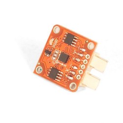
TinkerKit 2/3 Axis Accelerometer module
T000020
Nuevo
TinkerKit 2/3 Axis Accelerometer module
TinkerKit 2/3 Axis Accelerometer module
Un Acelerómetro es un dispositivo capaz de medir la aceleración. Es muy común en la electrónica de consumo (dispositivos electrónicos portátiles y videojuegos) ya que permite detectar el movimiento.
Output: este modulo restituye de 0V a 5V en cada uno de sus dos canales cuando varía la fuerza G (osea cuando esté en movimiento). A 0G coresponden aproximadamente un valor de 2.5V en los ejes X o Y. Si se conecta a una entrada de Arduino a través del TinkerKit Shield, el valor modulo en movimiento variarán de 0 a 1023.
Descripción del Módulo: en la parte trasera el módulo lleva dos amplificadores de señal y un LED verde que indica si el módulo está alimentado correctamente. El modulo se basa en el LIS344AL de ST Microelectronics, y es un acelerómetro con 3 ejes. Es posible obtener informaciónes sobre el tercer eje (Z) soldando un cable en el pin marcado "Z".
Este modulo es un SENSOR. El conector es un OUTPUT y tiene que ser conectado a los conectores INPUT del TinkerKit Shield.
ejemplo de codigo
/*
Double Analog input, Double analog output, serial output
Reads from two analog input pins, a T000020 Accelerometer Module connected to I0 and I1, maps the result to a range from 0 to 255
and uses the result to set the pulsewidth modulation (PWM) on two T010111 LED Modules connected on O0 and O1.
Also prints the results to the serial monitor.
created 29 Dec. 2008
Modified 4 Sep 2010
by Tom Igoe
modified 7 dec 2010
by Davide Gomba
This example code is in the public domain.
*/
#define O0 11
#define O1 10
#define O2 9
#define O3 6
#define O4 5
#define O5 3
#define I0 A0
#define I1 A1
#define I2 A2
#define I3 A3
#define I4 A4
#define I5 A5
// These constants won't change. They're used to give names
// to the pins used:
const int analogInPin1 = I0; // Analog input pin that the Accelerometer's first pin is attached to
const int analogInPin2 = I1; // Analog input pin that the Accelerometer's second pin is attached to
const int analogOutPin1= O0; // Analog output pin that the LED is attached to
const int analogOutPin2= O1; // Analog output pin that the LED is attached to
int sensorValue1 = 0; // value read from the Accelerometer's first pin
int sensorValue2 = 0; // value read from the Accelerometer's second pin
int outputValue1 = 0; // value output to the PWM (analog out)
int outputValue2 = 0; // value output to the PWM (analog out)
void setup() {
// initialize serial communications at 9600 bps:
Serial.begin(9600);
}
void loop() {
// read the both analog in values:
sensorValue1 = analogRead(analogInPin1);
sensorValue2 = analogRead(analogInPin2);
// map it to the range of the analog out:
outputValue1 = map(sensorValue1, 0, 1023, 0, 255);
outputValue2 = map(sensorValue2, 0, 1023, 0, 255);
// change the analog out value:
analogWrite(analogOutPin1, outputValue1);
analogWrite(analogOutPin2, outputValue2);
// print the results to the serial monitor:
Serial.print("accelerometer X = " );
Serial.print(sensorValue1);
Serial.print("t accelerometer Y = " );
Serial.print(sensorValue2);
Serial.print("t output 1 = ");
Serial.print(outputValue1);
Serial.print("t output 2 = ");
Serial.println(outputValue2);
// wait 10 milliseconds before the next loop
// for the analog-to-digital converter to settle
// after the last reading:
delay(10);

CORZOTECH - EASY LIFE FOR INTERACTION