No products
Product successfully added to your shopping cart
There are 0 items in your cart. There is 1 item in your cart.
Shields
Top sellers
-

Services
1,00 € -

4 Pin Dual-female...
0,85 € -

-

6 Pin Dual-female...
1,89 €
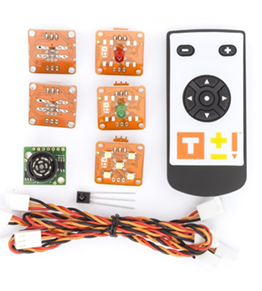
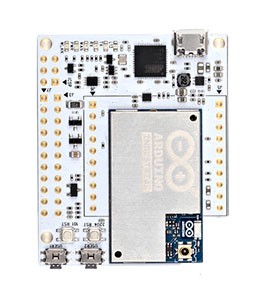

 View larger The picture may differ from the original

Description
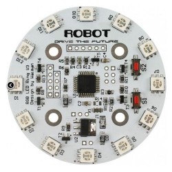
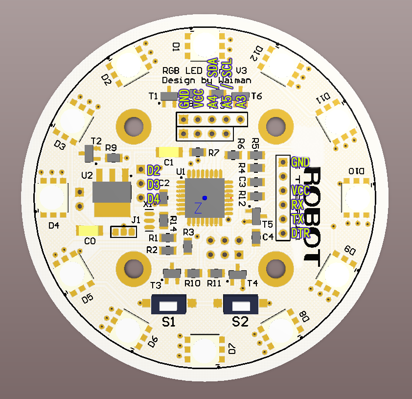
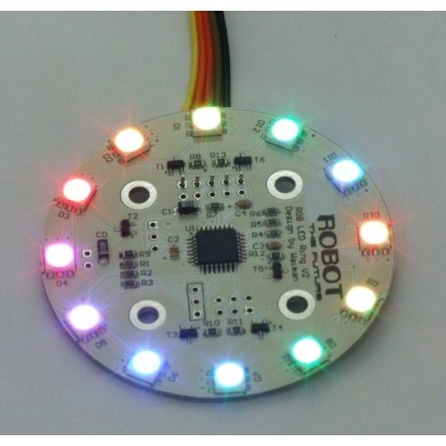
Cyclic RGBuino Shield has been upgraded to version 3.
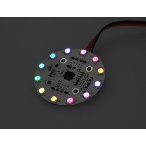
This is probably the most beautiful LED ring ever. Each led on the ring can be controlled seperatly on its brightness and colors (RGB). It comes with pre-burned bootloader which has several built in led scripts.
It allows I2C/Serial communication from any MCU and can be serially linked to make a beautiful Art piece via I2C.
It can be programmed using standard Arduino IDE by FTDI breakout board.
Specificiation
1、CPU: Atmega 168P (Lilypad Board in Arduino IDE)
2、Bootloader: Optiboot diecimila
3、Supply voltage : 5V
4、Output voltage : 5V
5、Interface : Serial/I2C/Digital pins
6、Push button x2
7、12 SMD RGB LED
8、Firmware upgradable
9、Stand-alone operation: No microcontroller needed for light script playback
Procedure
Cyclic RGBuino Shield ships with no pin headers. This gives you the option to solder the pins according to your project needs. Before starting to program the LED Ring you should solder the pin headers on to the board.
1) FTDI connection instructions
After soldering your pin headers, connect your Cyclic RGBuino Shield to the FTDI board as shown in the diagram
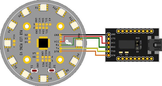
Caution : Only supply power to 1 of the 3 power pins provided at any one time.
Once you have connected the Cyclic RGBuino Shield to the FTDI breakout board connect the FTDI board to your PC. After windows has finished installing the drivers, find which com port it was assigned to by going to Control Panel and then Device Manager.
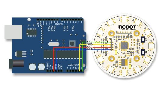
2) I2C connection instructions
Note : Do not connect 5V if already connected from the FTDI board
Connect your Arduino to the Rainbow Ring. Since we are providing power from the FTDI board do not plug in the 5V Vcc to the I2C side of the Rainbow Ring. The only 3 wires you need to connect are the SDA to pin 4, SCL to pin 5, and GND.
Prepare sketches and library
Note : This library has yet to be upgraded to be compatible with IDE V1.0 Please use IDE V0022
1、Download the Rar file with the source code and library.
2、Place the RGB_Ring_V3 library folder in : Arduino-0022Libraries
3、Please navigate to the following folder in your Arduino IDE folder: arduino-0022hardwarearduino
4、Open the boards.txt file located in this folder and at the bottom paste the information from (step 5)
5、From the downloaded RAR file open the folder: RGB_Ring_V3oards and programmers-arduinooards.txt (the information from this file needs to be added to the boards.txt file in your arduino-0022 folder, from step 4).
6、If your Arduino IDE is open, close it. Then re-open it and select the: "[Optiboot] Arduino Diecimila, Duemilanove, Nano, NG w/ ATmega168" option from "Tools>Boards" menu option
You should now be able to upload sketches to the Rainbow Ring V3
Setting up serial terminals
These sketches have been optimized to work with a serial terminal. You can use PuTTY or any other serial monitor. You can open a terminal window for each of the devices. Both are configured as follows:
your com port/ 9600 baud rate/ 8 data bits/ 1 stop bit/ no parity/ Hardware flow control
The hardware flow control will not affect the Arduino, but it is important for the Arduino Cyclic RGBuino Shield, this will reset the Ring every time the serial port is opened or closed. Once the serial monitor is open for each you should be greeted by the words "hello from Arduino" and "Hello from LED Ring" This will help you identify which is which. Now you can start passing commands to the Arduino Cyclic RGBuino Shield via the Arduino Serial terminal.
Arduino Cyclic RGBuino Shield interaction
The following are the commands used to control your Arduino Cyclic RGBuino Shield. Included are the parameters needed and the terminal command to execute each command.
//Term command
#set_led_rgb(LED, INT, INT, INT); //b The first parameter is the LED number from 0-11, INT = intensity 0-64
#set_led_unicolor(LED, RGB, Int); //u RGB = 0, 1, OR 2.
#set_all_rgb(R, G, B); //r int = intensity i.e.:RED 00, GREEN 25, BLUE 34: set_all_rgb(00, 25, 34);
#set_all_unicolor(RGB, Int); //a
#rotate(color, dir); //o Color, direction, color is set from 0-7 and rotation from 0-2
#clearCommand(); //- No parameters needed
#random_leds (); //x indicate how many LEDs to light and the delay between each
#fader (); //f how many times to repeat
#fader_hue (); //h how many times to repeat
#sequence(); //S how many times to repeat *NOTE: CAPITAL S
#color_wave (0) ; //w amount to increase ,delay
Each terminal command should be preceeded by a "c" and ended with an "s". These commands are case sensitve.
EXAMPLE:co029901s
This will send the command (c) rotate(o) the color Blue (02) times (99) clockwise (01) send (s)
Please study the sketch, it has been commented to give you a better idea of the functionality.
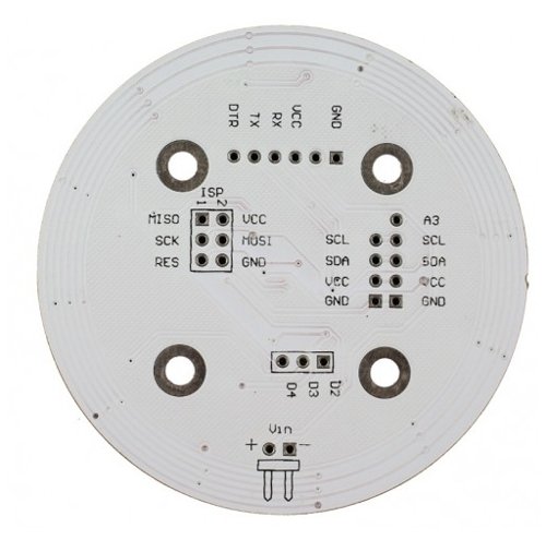
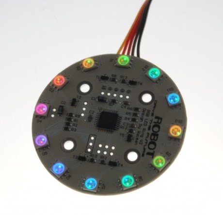
The back side :
Color enumeration
RED
GREEN
BLUE
YELLOW
TURQUOISE
FUCHSIA
WHITE
BLACK = OFF
Rotate CW = 1, CCW= 2
 41,90 €
 11,45 €
 32,14 €
 8,50 €
 22,94 €

CORZOTECH - EASY LIFE FOR INTERACTION